Fast Quote
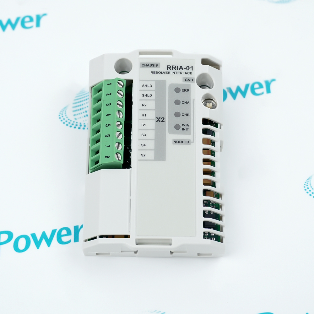
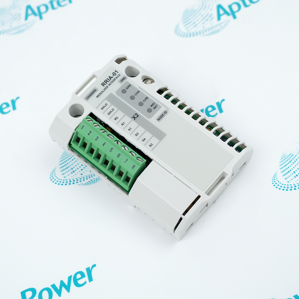
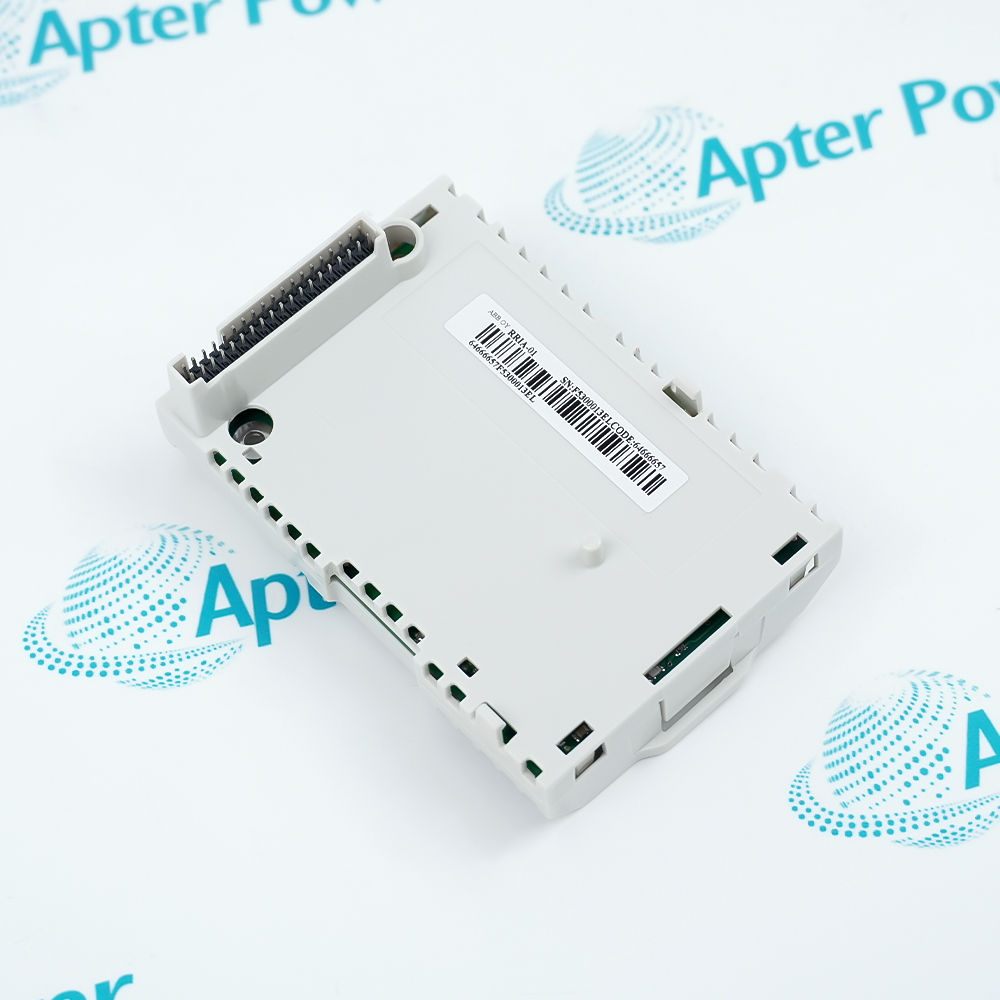

RRIA-01 commissioning begins by matching the connected resolver and motor-feedback arrangement to the selected ACS800 application program.
Configure the documented resolver transformation ratio, select one to four pole pairs, and use the applicable 10 kHz or 20 kHz excitation setting.
Before operation, check feedback-signal phasing, cable shielding and grounding, node addressing, and whether the module is installed directly in the RMIO board or through an AIMA-01 adapter.
Availability, condition, price, and shipping time for RRIA-01 are confirmed during quotation.
ABB RRIA-01 Resolver Interface Module Manuals, Datasheets, Links
 ABB RRIA-01 DatasheetBrowse ABB Drives Product ListingsReview Apter Power Service and Support Information
Important Notice: Other accessories, manuals, cables, calibration data, software, etc. are not included with this equipment unless listed in the above stock item description. All prices are shown in USD.


APTER.COM is an official website owned and operated by Apter Power Limited.All rights reserved.
Apter Power is not an authorized distributor or representative of the manufacturers featured on this website.All brand names and trademarks are the property of their respective owners.