AB 1756-RM
AB 1756-RM
AB 1756-RM
AB 1756-RM
AB 1756-RM
AB 1756-RM
Ask our team:
  • Phone: +86 181 0690 9650
  • E-Mail sales1@apterpower.com
  • Lifecycle status

    Discontinued

1756-RM

/ 4.9
1001 reviews | Need a Specific Revision?
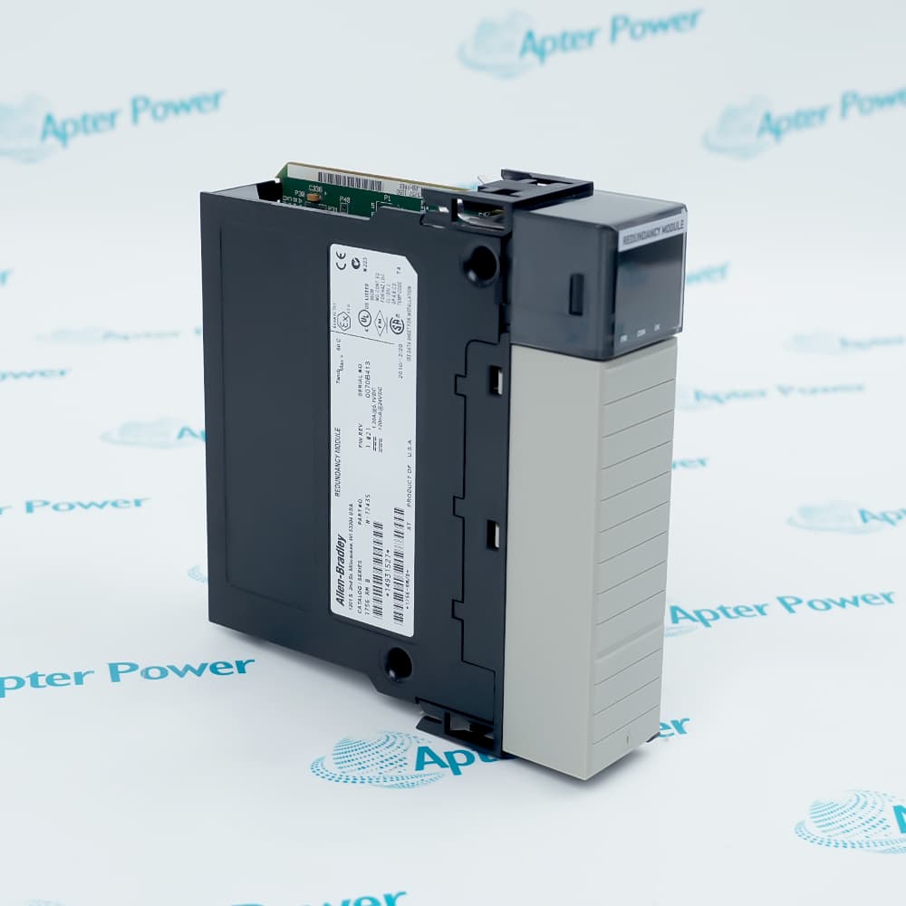
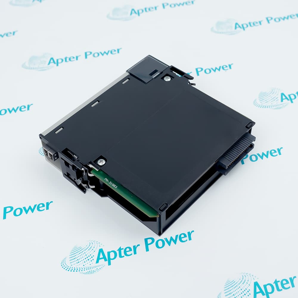
Allen-Bradley 1756-RM is a ControlLogix redundancy module for a documented paired redundant-controller architecture.
In Stock
Ships by Thursday, October 29
Fast Shipping Available
Get a quick price for 1756-RM
Quantity
*E-mail
Company
*Mobile
*Content
Upload (gif, jpg, jpeg, png, bmp, doc, docx, xls, xlsx, ppt, pdf, csv)

Technical specifications for 1756-RM

  • Manufacturer:
    Allen-Bradley
  • Part Number:
    1756-RM
  • Product Family:
    ControlLogix
  • Product Type:
    ControlLogix Redundancy Module
  • Stock:
    1
  • Placement:
    same slot in each redundant chassis
  • Supported controller families:
    ControlLogix 5560 and ControlLogix 5570
  • Maximum communication rate:
    100 Mbps
  • Modules Required:
    2, one in each redundant chassis
  • Current Draw at 1.2 V DC:
    4 mA
  • Current Draw at 5.1 V DC:
    1.2 A
  • Current Draw at 24 V DC:
    120 mA
  • Maximum Power Dissipation:
    9.0 W
  • Thermal Dissipation:
    31 BTU/hr
  • Connector Cable Options:
    1756-RMC1: 1 m; 1756-RMC3: 3 m; 1756-RMC10: 10 m
  • Operating Temperature:
    0…60 °C
  • Nonoperating Temperature:
    -40…+85 °C
  • Maximum Surrounding Air Temperature:
    60 °C
  • Relative Humidity:
    5…95%, noncondensing
  • Weight:
    0.29 kg
  • Tariff Code:
    9032900000
  • Country of origin:
    USA
  • Place of shipment:
    Xiamen, Fujian, China
By purchasing this item, you agree to the Terms & Conditions, ApterPower is not an authorized distributor for listed manufacturers or tradenames and therefore the manufacturer's warranty does not apply. All our products come with ApterPower's 1-year warranty.

More Information

Overview Manuals Paired Architecture Series and Firmware Recovery Preparation Application
  • Supports the documented ControlLogix redundant-controller architecture
  • Requires matched paired hardware, firmware, project, and chassis records
  • Must be installed and recovered as a redundant pair, not as an isolated module

1756-RM is an Allen-Bradley ControlLogix redundancy module for a documented redundant controller system.

Its function depends on a matched pair of controller chassis, redundancy modules, firmware, cabling, and synchronized controller application.

Capture the existing paired-system records and verify the installed Series before replacement, recovery, or migration planning.

Availability, condition, price, and shipping time for 1756-RM are confirmed during quotation.

Allen-Bradley 1756-RM ControlLogix Redundancy Module Manuals, Product Family, Links

Important Notice: Other accessories, manuals, cables, calibration data, software, etc. are not included with this equipment unless listed in the above stock item description. All prices are shown in USD.
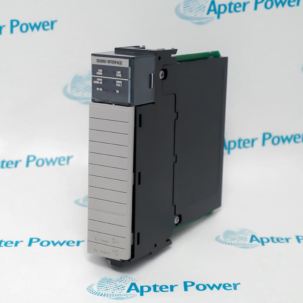
  • Install one redundancy module in each chassis of the documented redundant pair
  • Keep controller, chassis, module, cable, and project records aligned between both sides
  • Do not troubleshoot a redundant pair from one chassis in isolation
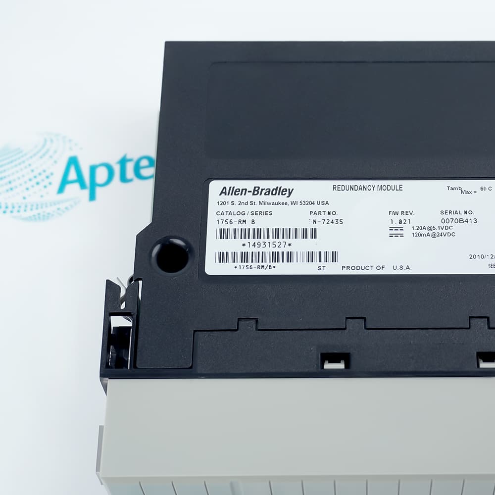
  • Read the installed module label and firmware record before selecting a replacement
  • Do not assign a Series from the base 1756-RM catalog number alone
  • Validate paired compatibility in the approved Rockwell Automation system record
  • Archive both controller projects and current redundancy status before maintenance
  • Record chassis positions, cabling, and all relevant network assignments
  • Return the pair through the documented synchronization and recovery procedure
  • ControlLogix 5560 redundant-controller systems using a matched 1756-RM pair
  • ControlLogix 5570 redundant-controller systems requiring synchronized chassis operation
  • Paired chassis systems using a direct 1756-RMCx single-mode fiber link for redundancy crossload and switchover
Description
1756-RM is a discontinued Allen-Bradley ControlLogix redundancy module for ControlLogix 5560 and 5570 redundant-controller systems.

A redundancy pair uses one 1756-RM in the same slot of each chassis, with matching catalog numbers and compatible Series and firmware, connected by the documented single-mode 1756-RMCx fiber link at up to 100 Mbps.

Before replacement, record both chassis configurations, controller projects, 1756-RM Series and firmware, cable catalog and routing, synchronization state, and RMCT settings, then follow the documented redundancy recovery procedure.
Revisions

Revision Part #

Also known as

1756-RM Ser A
1756-RM/A, Series A, Rev A
1756-RM Ser B
1756-RM/B, Series B, Rev B
Alternative Names
1756-RM 1756 RM 1756RM Allen-Bradley 1756-RM Rockwell Automation 1756-RM ControlLogix 1756-RM
Technical notes
1756-RM requires one matched module in the same slot of each ControlLogix 5560 or 5570 redundancy chassis; verify Series, firmware, 1756-RMCx single-mode fiber, synchronization status, and RMCT records before replacement.
Exceptional Service

Our Mission

  • 100% Satisfaction

    We believe expertise is priceless. With over 20 years of experience, and top engineers on staff, we can help you solve or avoid problems that threaten your business.
  • Trust Guaranteed

    Not only do we have a vast inventory, our team makes sure every piece of equipment is in working condition. Your purchases are also backed by our Warranty.
  • Expertise

    Time is money, especially when your equipment is down. We work quickly to get your equipment on its way so you can get it back up and running.

FAQS

The following is a list of questions commonly asked by our customers. Please contact us if you have a question about our process that is not answered below.
Can 1756-RM be installed in only one chassis of a redundant controller pair?
No. The documented redundant architecture requires one redundancy module in each chassis. Confirm the complete paired arrangement before energizing the system.
What must match between two 1756-RM redundant systems?
Record and verify the paired controller hardware, redundancy-module identity, firmware, chassis locations, cabling, and synchronized project before replacement work.
Why can both controllers appear healthy while Allen-Bradley 1756-RM redundancy does not establish?
Review the redundancy system as a pair: verify identical slot placement, matching 1756-RM catalog and Series, compatible firmware, direct fiber link, qualified chassis configurations, controller mode, and RMCT synchronization status.
Can a 1756-RM replacement be selected from the model number without inspecting Series information?
No. Official records include more than one Series entry. The installed Series and compatible firmware must be established from the actual equipment and approved system record.
What records should be saved before replacing 1756-RM in a running process?
Save the controller projects, redundancy status, firmware/Series records, chassis drawings, module locations, network records, and an approved recovery plan.
Can 1756-RM be substituted with 1756-RM2 solely because both provide controller redundancy?
No. Rockwell Automation migration documentation treats the RM/RMXT and RM2/RM2XT platforms as a planned migration subject, not an unverified direct interchange.
How should a repaired 1756-RM redundant pair be returned to service?
Follow the approved redundancy recovery procedure, verify synchronization and fault-free status, then perform controlled functional testing before relying on automatic operation.

Product Browsing History
