Ask our team:
  • Phone: +86 181 0690 9650
  • E-Mail sales1@apterpower.com
  • Lifecycle status

    Active / Available from OEM
    Apter Power checks the 190501-09-99-01 mounting, cable and approval configuration against the quotation record.

190501-09-99-01

/ 4.9
1001 reviews | Need a Specific Revision?
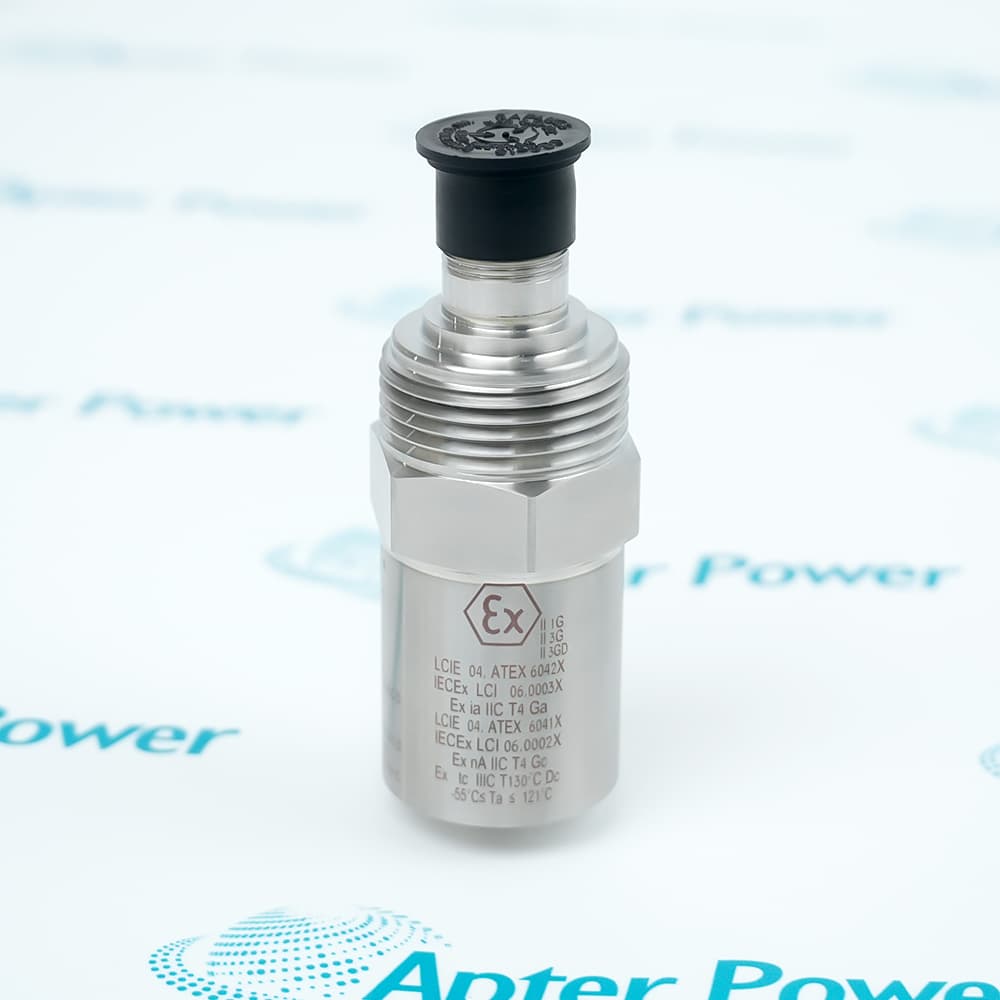
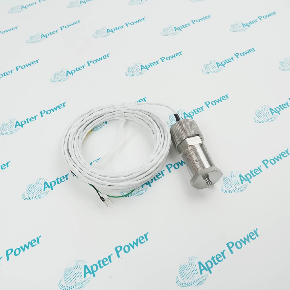
Bently Nevada 190501-09-99-01 is a low-frequency Velomitor CT velocity transducer with a 1/4-inch NPT plate stud, included 32-foot cable and hazardous-area approval option.
In Stock
Ships by Wednesday, October 28
Fast Shipping Available
Get a quick price for 190501-09-99-01
Quantity
*E-mail
Company
*Mobile
*Content
Upload (gif, jpg, jpeg, png, bmp, doc, docx, xls, xlsx, ppt, pdf, csv)

Technical specifications for 190501-09-99-01

  • Manufacturer:
    Bently Nevada
  • Part Number:
    190501-09-99-01
  • Product Family:
    190501 Velomitor CT Transducer
  • Product Type:
    Velomitor CT Velocity Transducer
  • Stock:
    1
  • Ordering Base Number:
    190501 — Velomitor CT velocity transducer
  • Mounting Hardware Option:
    09 — plate stud, 3/8-24 to 1/4-in NPT
  • Connection Option:
    99 — unit with included 32-foot cable
  • Agency Approval Option:
    01 — hazardous-area approval configuration; verify delivered marking
  • Sensitivity:
    3.94 mV/mm/s (100 mV/in/s), ±5%
  • Frequency Response:
    3.0 to 900 Hz ±1.0 dB; 1.5 Hz to 1.0 kHz ±3.0 dB
  • Velocity Range:
    63.5 mm/s peak (2.5 in/s peak)
  • Output Bias Voltage:
    10.1 VDC ±1.0 VDC, pin A referenced to pin B
  • Operating Temperature:
    -40°C to +85°C (-40°F to +185°F)
  • Case Material:
    316L stainless steel
  • Mounting Torque:
    4.5 N·m ±0.6 N·m (40 in-lbf ±5 in-lbf)
  • Mounting Orientation:
    Any orientation
  • Tariff Code:
    Please confirm the destination before shipping
  • Country of origin:
    USA
  • Place of shipment:
    Xiamen,Fujian,China
By purchasing this item, you agree to the Terms & Conditions, ApterPower is not an authorized distributor for listed manufacturers or tradenames and therefore the manufacturer's warranty does not apply. All our products come with ApterPower's 1-year warranty.

More Information

Overview Manuals Mounting Review Signal Integration Fault Isolation Product Applications

Features:

  • Low-frequency velocity response: The transducer covers fan assemblies beginning at 90 rpm and extends through motor and speed-reducer vibration components.
  • Defined mounting hardware: The plate stud adapts the transducer to a 1/4-inch NPT mounting point.
  • Long included lead: Connection option 99 supplies a 32-foot cable as part of the ordered configuration.
The Velomitor CT converts casing vibration velocity into an electrical signal for machinery condition or protection channels.

Its usefulness depends on a rigid mounting point that carries the rotor-related vibration into the transducer body.

The exact option code also determines the mounting adapter, cable scope and approval identity needed at receiving.

Apter Power can help confirm the Bently Nevada 190501-09-99-01 plate stud, included cable, approval marking and monitoring-input requirements before quotation.
Bently Nevada 190501-09-99-01 Velomitor CT Velocity Transducer Manuals,Datasheets,Link
Important Notice: Other accessories, manuals, cables, calibration data, software, etc. are not included with this equipment unless listed in the above stock item description. All prices are shown in USD.
  • Machine location: Select a bearing housing or casing point that transmits the vibration of interest.
  • Surface preparation: Keep the mounting face clean, flat and rigid so the transducer follows machine motion.
  • Stud identity: Preserve the 3/8-24 to 1/4-inch NPT plate-stud arrangement defined by option 09.
  • Torque control: Apply the published mounting torque without loading the cable or connector.
  • Polarity: Account for pin A becoming positive relative to pin B when velocity is from base to top.
  • Input bias: Verify the monitor channel accepts the documented 10.1 VDC nominal bias.
  • Cable route: Protect the included 32-foot lead from tensile load, abrasion and high-noise power wiring.
  • Hazardous area: Match the delivered approval marking, entity limits and barrier arrangement to the site design.
  • Low reading: Check mounting stiffness and machine-to-casing vibration transfer before condemning the sensor.
  • False signal: Inspect the mounting surface, cable shielding, connector condition and local structural resonance.
  • Bias fault: Compare channel voltage and polarity with the wiring record to separate sensor and input problems.
  • Trend comparison: Record fan speed, motor state and reducer condition when comparing old and replacement signals.
  • Cooling-tower fans: Monitors low-frequency casing vibration on fan, bearing and drive assemblies.
  • Air-cooled heat exchangers: Tracks velocity changes associated with fan, motor and speed reducer behavior.
  • Slow-speed machinery: Provides a velocity signal where the documented operating speed is at least 90 rpm.
  • Hazardous-area monitoring: Supports approved installations when the exact marking and entity-control drawing are observed.
Description
190501-09-99-01 measures casing vibration velocity on cooling-tower and air-cooled heat-exchanger fan assemblies operating at or above 90 rpm, including vibration associated with the fan motor and speed reducer.

The mounting code on 190501-09-99-01 specifies a plate stud that adapts the transducer’s 3/8-24 mounting interface to 1/4-inch NPT, while connection option 99 includes a 32-foot cable.

For reliable use of 190501-09-99-01, the mounting location must transmit meaningful rotor vibration to the casing, and the approval marking, cable route, PLC or monitor input and alarm strategy must be checked as one installation.
Alternative Names
190501099901 190501 09 99 01
Technical notes
190501-09-99-01 must be mounted on a bearing housing or machine casing that transmits the vibration of interest. A poor surface, loose plate stud or flexible structure can attenuate response or create false signals. Verify polarity, cable shielding, input bias and hazardous-area installation before restoring protection alarms.
Exceptional Service

Our Mission

  • 100% Satisfaction

    We believe expertise is priceless. With over 20 years of experience, and top engineers on staff, we can help you solve or avoid problems that threaten your business.
  • Trust Guaranteed

    Not only do we have a vast inventory, our team makes sure every piece of equipment is in working condition. Your purchases are also backed by our Warranty.
  • Expertise

    Time is money, especially when your equipment is down. We work quickly to get your equipment on its way so you can get it back up and running.

FAQS

The following is a list of questions commonly asked by our customers. Please contact us if you have a question about our process that is not answered below.
A cooling-tower fan runs at 100 rpm. Is 190501-09-99-01 within its intended speed range?
Yes, the documented application starts at 90 rpm, with 100 to 300 rpm described as typical. The mounting point must still transmit the fan train vibration into the casing.
The signal from 190501-09-99-01 is lower than a portable measurement nearby. What should be checked first?
Inspect mounting rigidity, surface condition and structural transmission before changing alarm settings. A flexible or poorly coupled location can attenuate the measured casing velocity.
Does option 99 on 190501-09-99-01 mean the 32-foot cable must be ordered separately?
No. Option 99 defines a unit with the 32-foot cable included. Confirm that the received scope contains the cable and that its routing is suitable.
Can 190501-09-99-01 replace a transducer mounted through a different thread without review?
No. This configuration uses the option 09 plate stud from 3/8-24 to 1/4-inch NPT. Verify the existing mounting interface and the required mechanical coupling.
A monitor reports an abnormal bias after installing 190501-09-99-01. Which checks separate wiring from vibration?
Measure the channel bias and polarity, inspect connector pinning and shielding, then compare the dynamic signal. A bias fault should be resolved before interpreting machine vibration.
The destination certificate requires a particular hazardous-area marking for 190501-09-99-01. Is the suffix alone sufficient?
No. Confirm the delivered nameplate, certificate scope and entity parameters for the destination. The order suffix identifies the approval configuration but does not replace site verification.

Product Browsing History