Features:
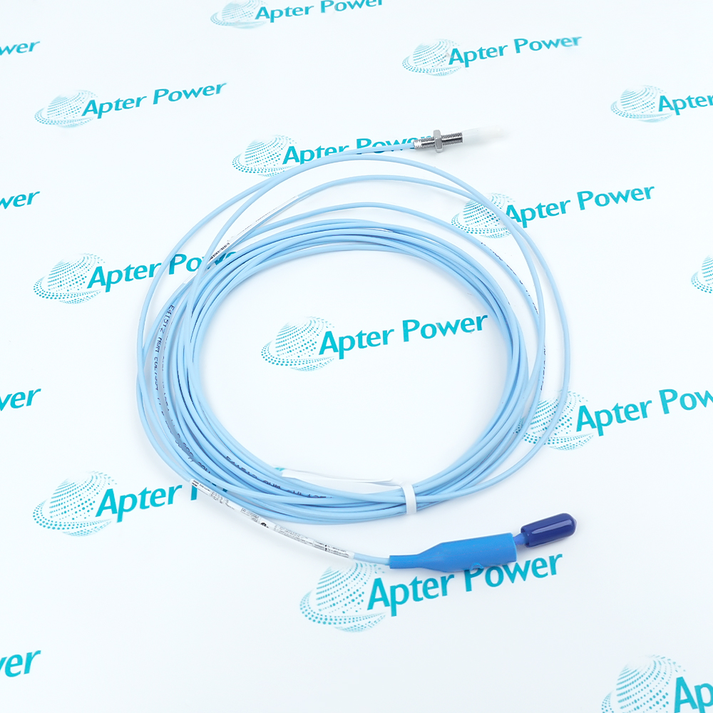
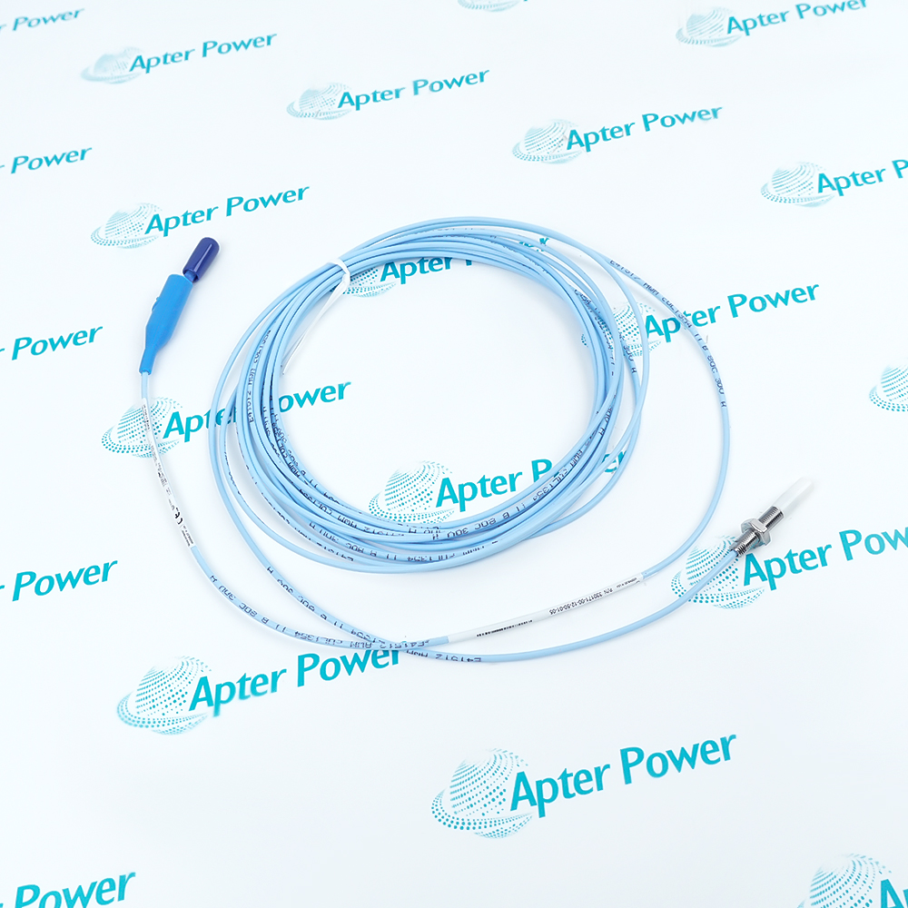
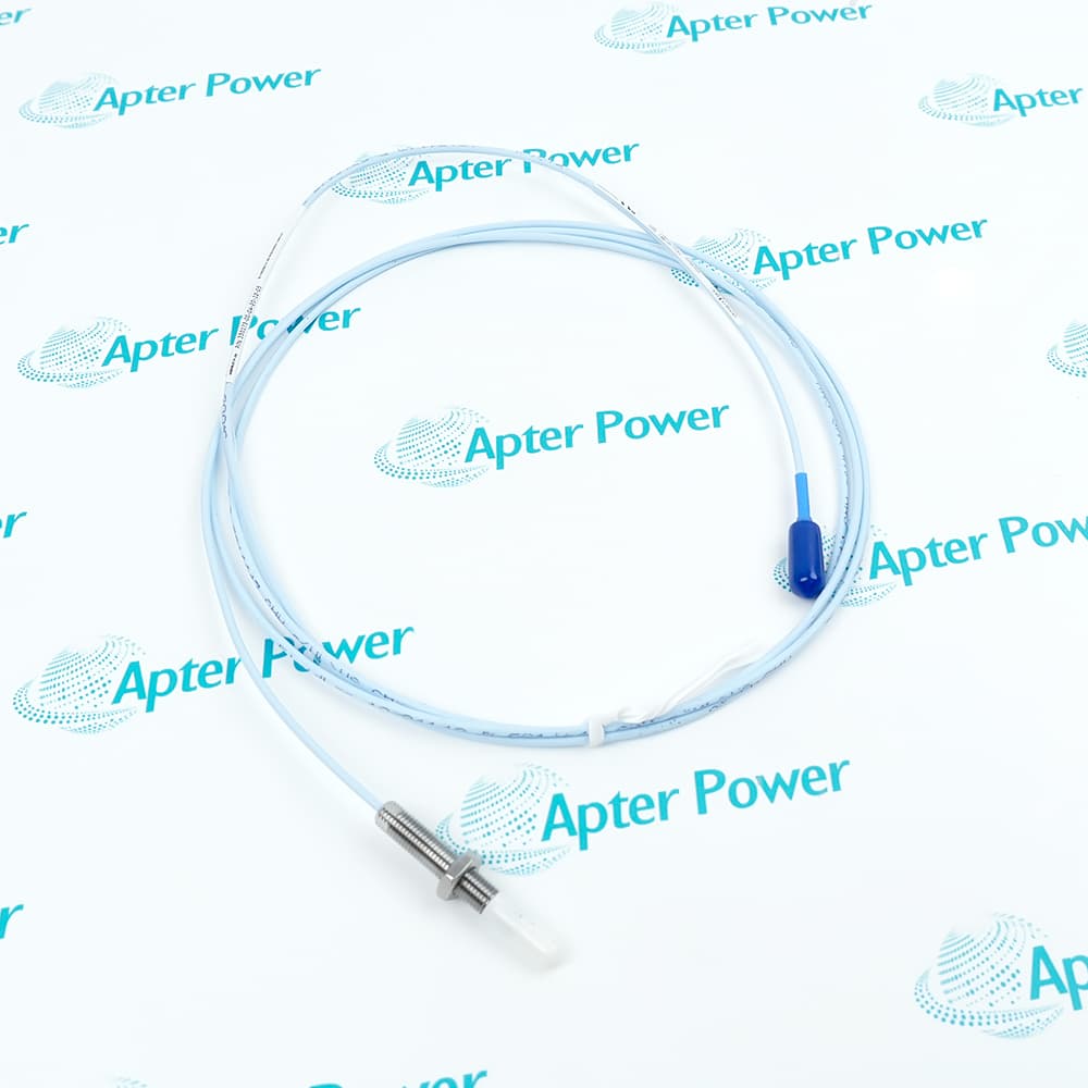
- Five-metre integral lead for a remote cable connection point
- Fully threaded 1.2-inch case with no unthreaded section
- Protected miniature ClickLoc connector on standard cable
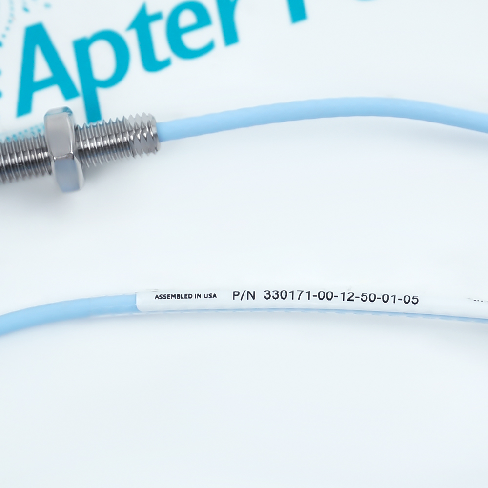
The 330171-00-12-50-01-05 combines the shortest listed case block with a long attached lead, separating the sensing position from the extension-cable joint.
Its 5 mm PPS tip operates over the documented two-millimetre linear span when the shaft surface, gap and matched electronics satisfy the system requirements.
Because the probe cable is not armored, the route must protect the lead from mechanical damage while preserving the specified minimum bend radius.
The Bently Nevada 330171-00-12-50-01-05 3300 5 mm Probe may still be available for purchase and support from Apter Power beyond End-Of-Life (EOL) by the manufacturer (OEM).
Bently Nevada 330171-00-12-50-01-05 3300 5 mm Probe Manuals,Datasheets,Link
Important Notice: Other accessories, manuals, cables, calibration data, software, etc. are not included with this equipment unless listed in the above stock item description. All prices are shown in USD.
Five-Metre Lead Arrangement
- Probe end: The integral cable begins at the 5 mm sensing tip and remains part of the probe assembly.
- Cable reach: A 5.0 m attached lead places the detachable joint away from the mounting point.
- Cable type: The standard 75-ohm triaxial construction uses FEP insulation and no armor.
- Connector end: The miniature ClickLoc connector provides the junction to the remaining transducer loop.
Calibrated System Matching
- System length: Confirm whether the connected Proximitor Sensor is configured for the documented complete loop length.
- Extension choice: Select only the extension length that completes that probe-to-electronics distance.
- Connector check: Seat the ClickLoc joint before checking gap or machine readings.
- Configuration control: Do not treat the 5.0 m integral lead as interchangeable with a 0.5 m probe lead.
Protected Cable Joint
- Connector style: The miniature coaxial ClickLoc interface joins the probe lead to the extension cable.
- Protector: Order block 01 includes the connector protector around the detachable joint.
- Strain control: Support the cable route so the joint does not carry probe-side tension.
- Inspection: Check seating and protector position whenever the loop has been disconnected.
Gap and Target Conditions
- Reference point: Use the 1.27 mm recommended gap as the starting position.
- Linear span: Keep relative movement between 0.25 and 2.3 mm at the probe tip.
- Target diameter: Provide a flat conductive face at least 15.2 mm across.
- Bandwidth: The matched system covers static position through 10 kHz within the stated response tolerance.