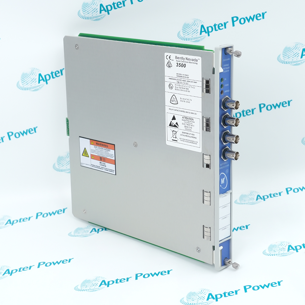
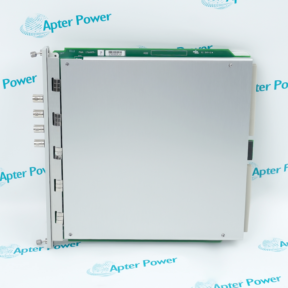
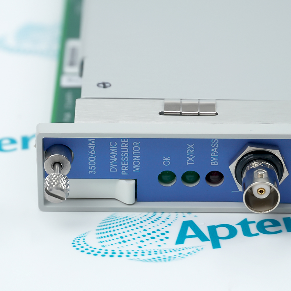
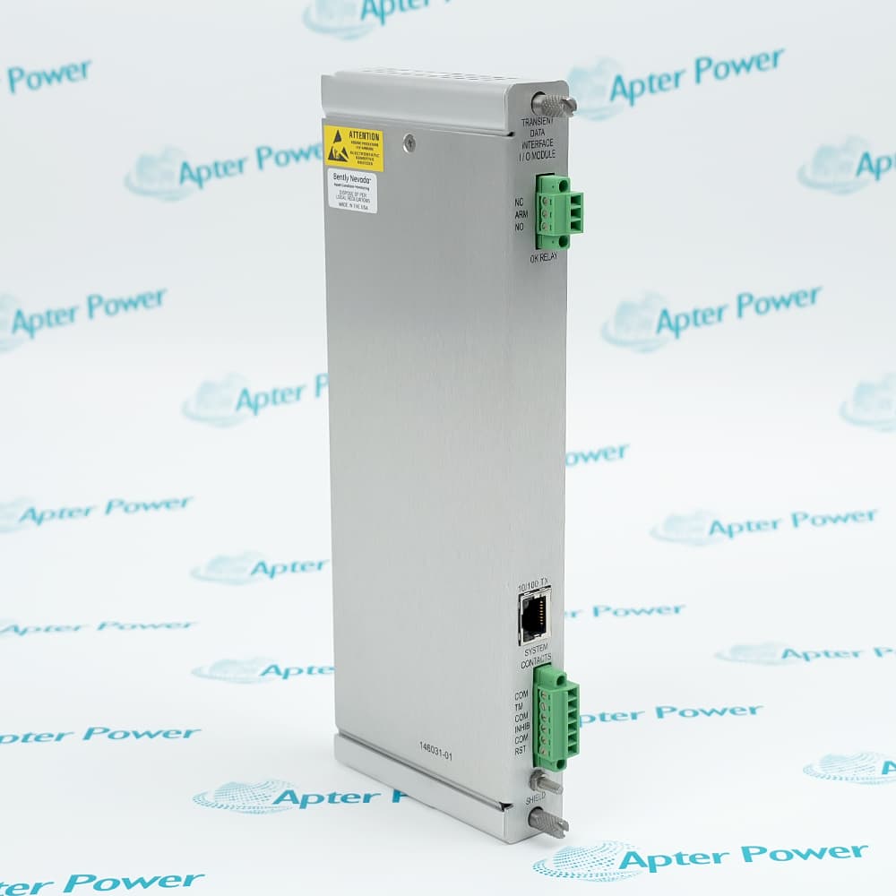
Features:
- Conditions four dynamic pressure transducer channels in one full-height 3500 rack slot.
- Pairs channels 1–2 and 3–4 for frequency-filter configuration and alarm processing.
- Provides front buffered signals and independent 4–20 mA recorder outputs for external checks.
Bently Nevada 3500/64M 176449-05 links dynamic pressure inputs to the 3500 rack alarm structure.
Each channel has a measurement path, buffered test point and recorder-output path with distinct electrical loading.
Filter pairing, cascade routing and alarm delay settings determine how a field waveform becomes a protection decision.
The Bently Nevada 3500/64M 176449-05 Four-Channel Dynamic Pressure Monitor is supported by current OEM technical documentation.
Bently Nevada 3500/64M 176449-05 Dynamic Pressure Monitor Manuals,Datasheets,Link
Important Notice: Other accessories, manuals, cables, calibration data, software, etc. are not included with this equipment unless listed in the above stock item description. All prices are shown in USD.
Four Channels Organized as Two Filter Groups
- First pair: Channels 1 and 2 share one frequency-filter selection.
- Second pair: Channels 3 and 4 share the other frequency-filter selection.
- Separate measurement: Each channel still keeps its own conditioned value, buffered signal and recorder output.
- Separate decisions: Alert and danger setpoints remain channel-specific even though filter selection is paired.
Selecting the Measurement Band
- Low-frequency path: The lower band passes pressure pulsation content from its high-pass point to the selected low-pass boundary.
- High-frequency path: The higher band shifts measurement toward faster combustion or pressure events.
- Open upper path: Removing the low-pass selection extends the documented upper response beyond the normal low-band setting.
- Line rejection: The selected 50 or 60 Hz notch suppresses power-frequency interference without redefining the channel pair.
Routing a Processed Channel to Cascade
- Source channel: Cascade operation starts from a configured monitor channel rather than an additional field transducer.
- Signal handoff: The chosen source is routed into the receiving processing path after its own input conditioning.
- Setting dependency: The observed result depends on both the source-channel settings and the downstream filter arrangement.
- Diagnostic check: A missing or unexpected cascade value requires checking source validity, routing selection and receiving-channel status together.
From Setpoint Crossing to Rack Alarm
- Value comparison: Each processed channel value is compared independently with its configured alert and danger thresholds.
- Accuracy boundary: The documented setpoint accuracy defines how closely the comparison follows full-scale value.
- Delay qualification: A threshold excursion must persist for the configured delay before the alarm state changes.
- Rack participation: Bypass and invalid-monitor states determine whether that channel contributes to rack protection.
- External indication: The alarm result is reported through the 3500 rack while buffered and recorder outputs remain separate signal paths.