MUL-D2
MUL-D2
MUL-D2
MUL-D2
MUL-D2
MUL-D2
Ask our team:
  • Phone: +86 181 0690 9650
  • E-Mail info@apterpower.com
  • Lifecycle status

    Discontinued / Obsolete by OEM
    Apter Power supports exact MUL-D2 Version 01 identification and legacy-spares sourcing.

MUL-D2

/ 4.9
1001 reviews | Need a Specific Revision?
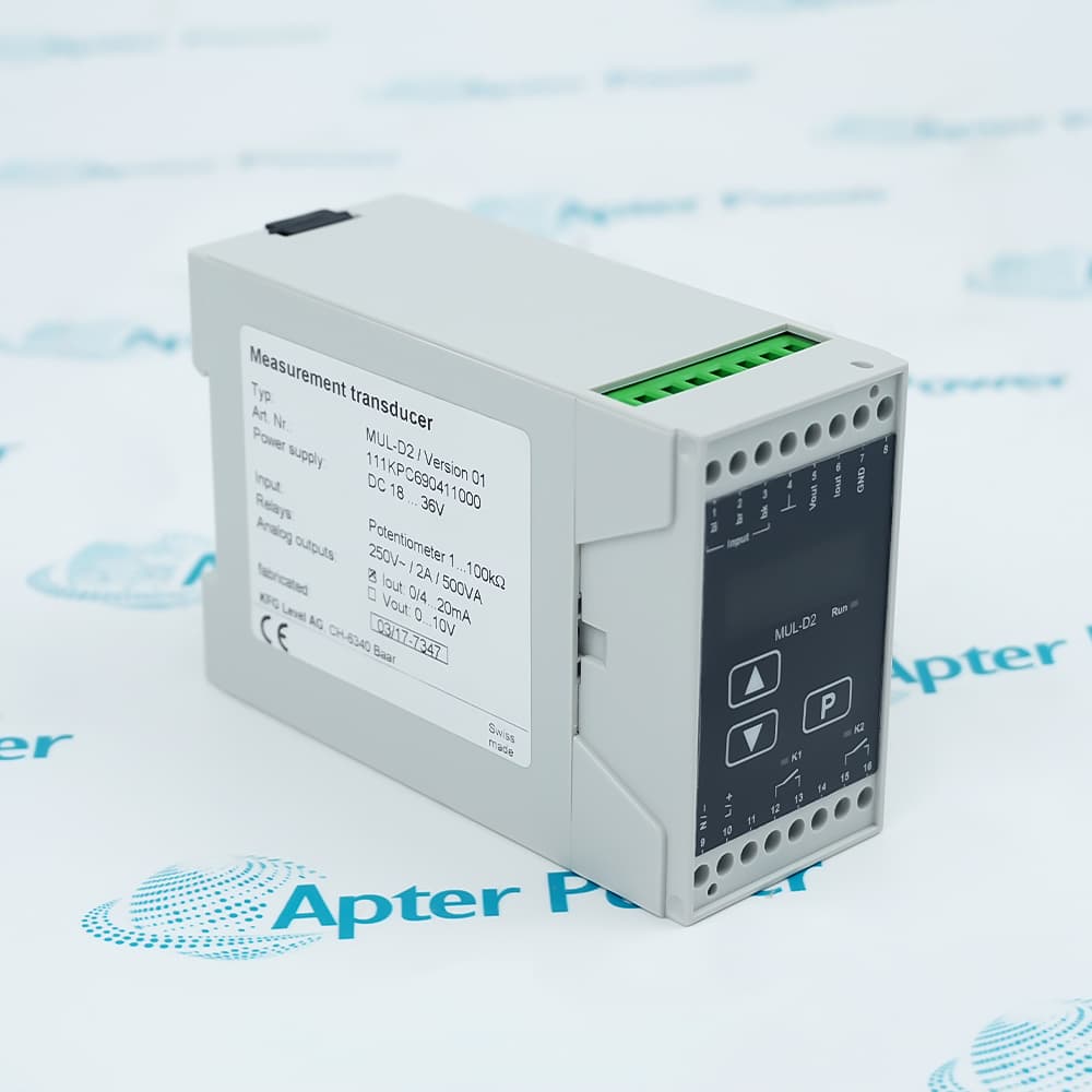
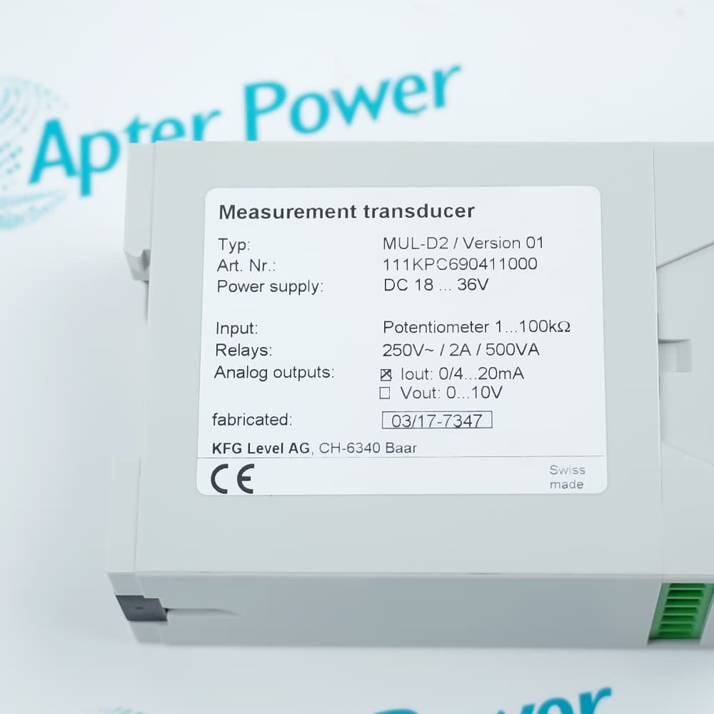
KFG LEVEL MUL-D2 is a Version 01 measurement transducer for a 1–100 kΩ potentiometer input, 0/4–20 mA output, and relay switching.
In Stock
Ships by Saturday, October 17
Fast Shipping Available
Get a quick price for MUL-D2
Quantity
*E-mail
Company
*Mobile
*Content
Upload (gif, jpg, jpeg, png, bmp, doc, docx, xls, xlsx, ppt, pdf, csv)

Technical specifications for MUL-D2

  • Manufacturer:
    KFG LEVEL
  • Part Number:
    MUL-D2
  • Product Family:
    KFG LEVEL
  • Product Type:
    Measurement Transducer
  • Stock:
    1
  • Version:
    01
  • Article Number:
    111KPC690411000
  • Supply Voltage:
    18–36 V DC
  • Input Signal:
    Potentiometer, 1–100 kΩ
  • Analog Output:
    0/4–20 mA
  • Relay Contact Rating:
    250 Vac / 2 A / 500 VA
  • Certification Marking:
    CE
  • Weight:
    0.2 kg
  • Estimated shipping dimensions:
    4.5x11x7.5cm
  • Tariff Code:
    Please confirm the destination before shipping
  • Country of origin:
    Switzerland
  • Place of shipment:
    Xiamen,Fujian,China
By purchasing this item, you agree to the Terms & Conditions, ApterPower is not an authorized distributor for listed manufacturers or tradenames and therefore the manufacturer's warranty does not apply. All our products come with ApterPower's 1-year warranty.

More Information

Overview Manuals Signal Path Relay Boundary Ordering Identity Applications

Features:

  • Measurement bridge: Converts a potentiometer-based measurement into an analog current path for the receiving control system.
  • Two panel functions: Places analog conversion and a relay function in one labeled measurement transducer.
  • Traceable configuration: Version 01 and article number 111KPC690411000 identify the installed build for spare-part review.
MUL-D2 sits between a resistive sensing element and a current-input device, allowing the position represented by the potentiometer to be carried as an analog loop signal.

The analog path and the relay function serve different roles in the surrounding panel; operation of one should not be treated as proof that the other path is correct.

For procurement and incoming inspection, match the complete model with Version 01 and article number 111KPC690411000 rather than relying on enclosure appearance alone.

Apter Power supports exact-model document review, quotation, and procurement for the KFG LEVEL MUL-D2 Measurement Transducer.
KFG LEVEL MUL-D2 Measurement Transducer Manuals,Datasheets,Link
Important Notice: No qualified exact-model English PDF is attached. Use the complete product model in every document request.
  • Sensor side: MUL-D2 receives the changing resistance from a potentiometer-based sensing element.
  • Conversion stage: The transducer changes that resistive measurement into an analog current signal for downstream equipment.
  • Channel boundary: The resistance input and current output are different circuit functions, so a reading on one side does not prove the other side is operating.
  • Fault isolation: Separate the sensing element, transducer power and receiving channel when tracing a measurement-loop fault.
  • Electrical boundary: The nameplate rating defines the relay contact limit, not the intended load or switching sequence.
  • Independent function: Relay operation and analog conversion should be assessed as separate paths during maintenance.
  • Load decision: Compare the real load and its inrush with the marked contact boundary before returning the circuit to service.
  • Logic scope: The nameplate does not define relay setpoints or process logic, so retain the installed wiring and control record during diagnosis.
  • Primary model: Use MUL-D2 as the exact product identity on the purchase request and receiving record.
  • Version marker: Version 01 identifies the labeled build represented on this page.
  • Article number: Keep 111KPC690411000 with the model to reduce ambiguity during sourcing and incoming inspection.
  • Configuration check: Use the selected current-output marking as a tie-breaker when a visually similar transducer is offered.
  • Potentiometer feedback: Converts a resistive position measurement into an analog current signal.
  • Panel measurement loops: Provides the conversion stage between a potentiometer-based sensor and current-input control equipment.
  • Combined panel functions: Fits measurement arrangements that use the unit's analog path together with its labeled relay function.
Description
In a control panel, MUL-D2 forms the conversion stage between a potentiometer-based sensing element and an analog current-input device. The receiving system can work with a standardized current signal while the sensing side remains a resistive measurement.

The Version 01 build of MUL-D2 combines the measurement path with a relay function in one labeled unit. Keeping the analog and switching roles tied to the same component helps maintenance teams trace each circuit without assuming that one function proves the other is operating.

For a replacement request, MUL-D2 should be identified with Version 01 and article number 111KPC690411000. Retaining both identifiers alongside the model improves purchasing accuracy when similar KFG Level transducers are present in an installed panel.
Alternative Names
MULD2 MUL D2 KFG LEVEL MUL-D2 111KPC690411000
Technical notes
The MUL-D2 nameplate selects the 0/4–20 mA output; the adjacent 0–10 V option is not marked for this unit. Confirm the receiving input type before wiring, keep the 18–36 V DC supply separate from signal terminals, and verify relay load characteristics remain within the listed 250 Vac, 2 A, 500 VA rating.
Exceptional Service

Our Mission

  • 100% Satisfaction

    We believe expertise is priceless. With over 20 years of experience, and top engineers on staff, we can help you solve or avoid problems that threaten your business.
  • Trust Guaranteed

    Not only do we have a vast inventory, our team makes sure every piece of equipment is in working condition. Your purchases are also backed by our Warranty.
  • Expertise

    Time is money, especially when your equipment is down. We work quickly to get your equipment on its way so you can get it back up and running.

FAQS

The following is a list of questions commonly asked by our customers. Please contact us if you have a question about our process that is not answered below.
Purchasing receives a unit marked MUL-D2 but cannot read the Version or article number. Can it be accepted as the requested spare?
No. Hold the item until Version 01 and article number 111KPC690411000 are verified; the model text alone does not establish the same labeled configuration.
During commissioning, the potentiometer connected to MUL-D2 changes resistance but the controller reading does not move. Where should diagnosis begin?
Begin at the conversion boundary. A changing resistance confirms the sensing side only; then prove transducer power, the analog current output and the receiving channel as separate stages.
The relay on MUL-D2 switches, yet the analog reading is absent. Does the relay response prove the measurement channel is healthy?
No. The relay and analog paths perform different functions, so diagnose the current-output path independently instead of using relay action as evidence of signal conversion.
Only a 12 VDC control supply is available when MUL-D2 is being commissioned. Should the team continue?
No. The labeled supply range starts at 18 V DC; provide a source within the marked range before evaluating the measurement or relay functions.
A maintenance team wants to connect an active 4–20 mA transmitter to the input of MUL-D2. Is that the correct sensor type?
No. The labeled input is for a potentiometer, not an active current transmitter. Stop the connection and select an input stage intended for the installed sensor type.
The load current is below the relay amperage marked on MUL-D2, but the load has high inrush. Is current alone enough to approve the connection?
No. The marked contact boundary includes both current and apparent-power limits; the real load, inrush and protective arrangement must remain within the applicable contact rating.

Product Browsing History