Features:
- Filtered power stage: Uses an integrated Class A line filter for the specified SINAMICS G120 installation.
- Overload flexibility: Provides separate low-overload and high-overload ratings for different load profiles.
- Dynamic braking: Includes the braking chopper needed to switch a correctly sized external resistor.
This article is the motor power stage; control and operator functions are supplied separately through the selected SINAMICS components.
Duty selection should follow operating current, acceleration demand and cycle timing instead of motor power alone.
Cabinet cooling, motor-cable length, grounding and braking-resistor sizing remain installation-level decisions.
Apter Power supports Siemens 6SL3210-1PE21-1AL0 PM240-2 sourcing with quotations, official documentation and SINAMICS G120 configuration matching.
Siemens 6SL3210-1PE21-1AL0 SINAMICS G120 PM240-2 Power Module Manuals,Datasheets,Link
Important Notice: The PDF and internal resources support product identification, installation planning and configuration review.
- Line input: Match a 3 AC 380–480 V ±10% supply at 47–63 Hz.
- Low-overload duty: Use the 4 kW and 10.2 A rating only with the stated 110% and 150% overload cycle.
- High-overload duty: Use the 3 kW and 7.7 A rating where the stated 150% and 200% overload cycle is required.
- Peak current: Keep the operating profile within the 15.4 A maximum output current.
- Enclosure: Treat the IP20 / UL open-type module as protected cabinet equipment.
- Cooling: Preserve the internal-air-cooling path and the specified 0.009 m³/s airflow.
- Temperature: Apply the -10 to +40°C LO limit or -10 to +50°C HO limit for the selected duty.
- Altitude: Use 1,000 m as the published installation-altitude reference before checking any required derating.
- Power terminals: Accept 1.5–6 mm² conductors for both line and motor connections.
- Shielded cable: Keep the motor lead within the published 50 m maximum.
- Unshielded cable: Keep the motor lead within the published 100 m maximum.
- EMC boundary: Complete cabinet bonding, shield termination and grounding even though the module has an integrated Class A filter.
- Conveyors: Evaluate high-overload duty where starting torque and repeated acceleration dominate the cycle.
- Pumps and fans: Evaluate low-overload duty only after the load curve and operating current are confirmed.
- Braking loads: Coordinate the integrated chopper with a resistor sized for regenerated energy and stop frequency.
- Retrofit panels: Match the FSB format, line supply, Control Unit, motor cable and cooling arrangement before exchange.
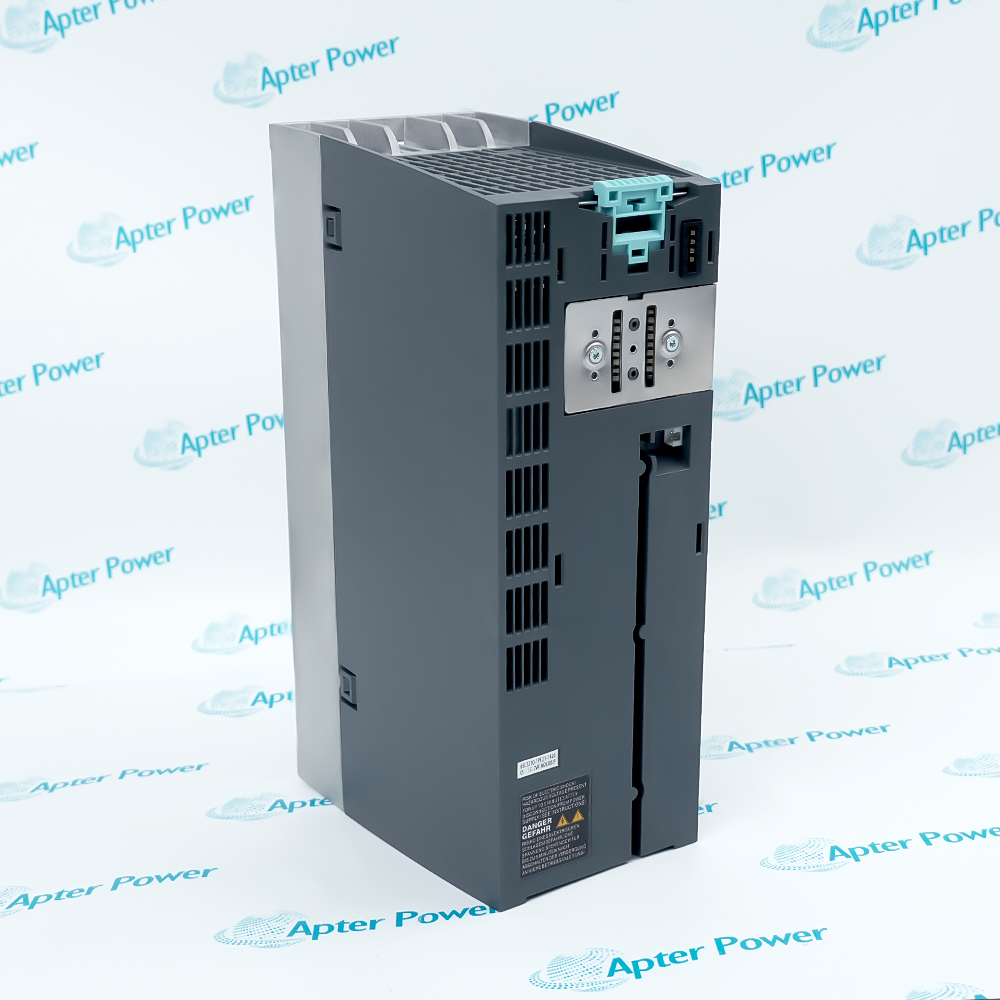
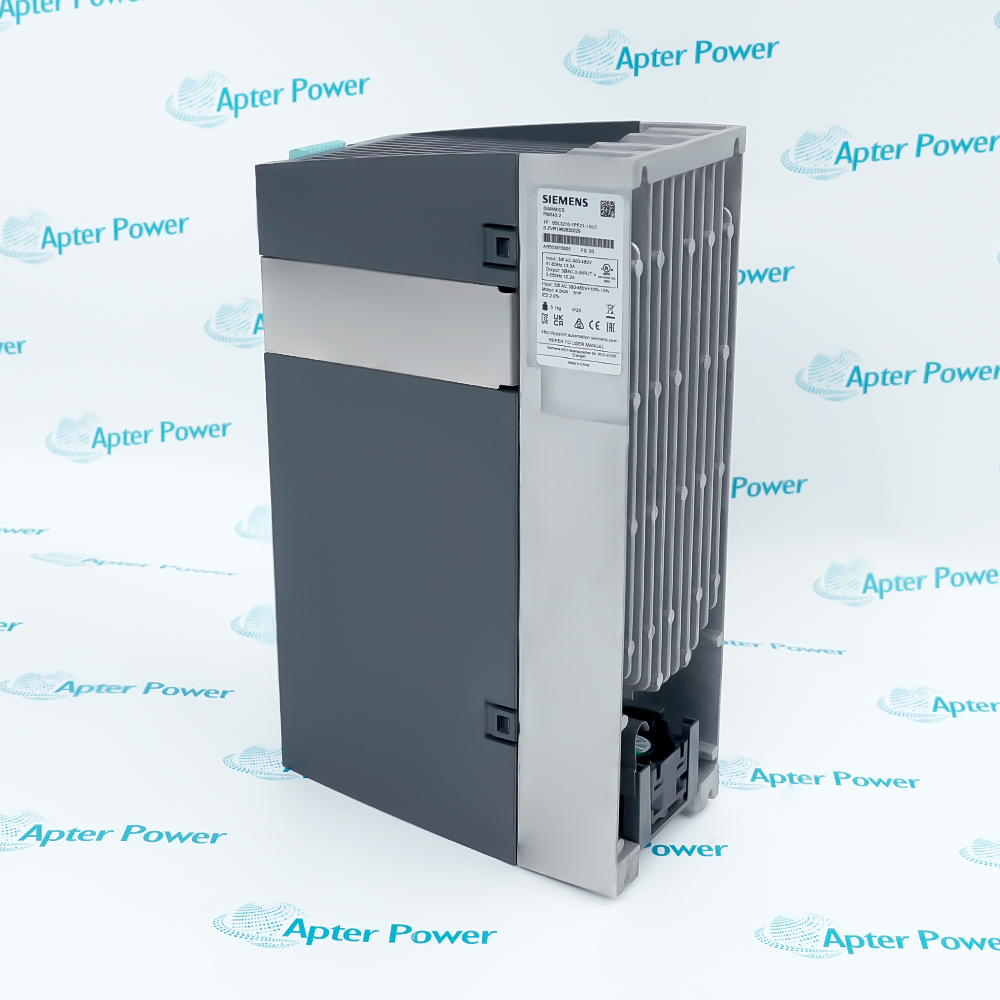
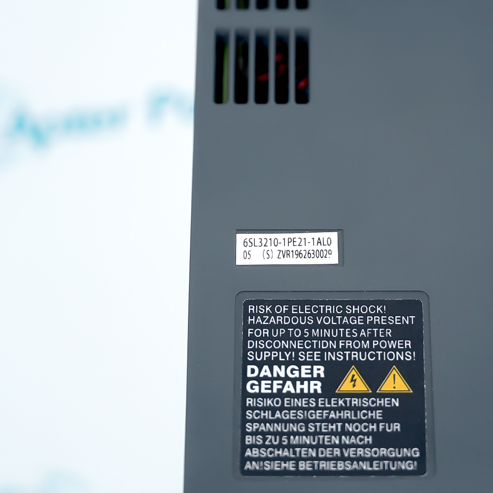

 6SL3210-1PE21-1AL0 Datasheet

