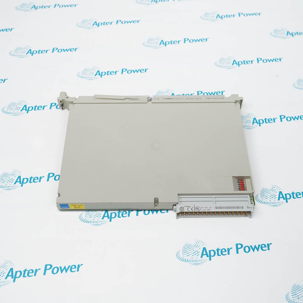
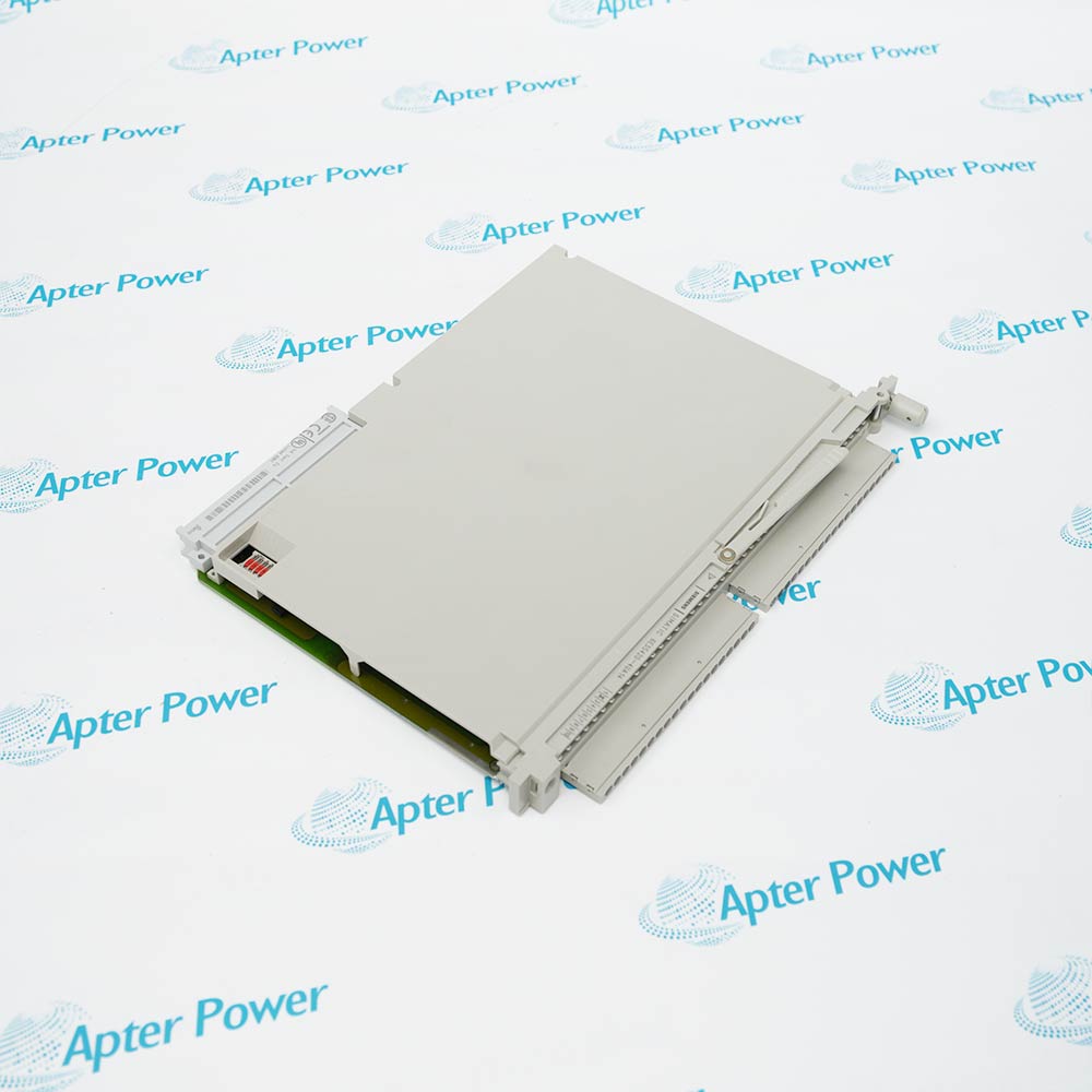
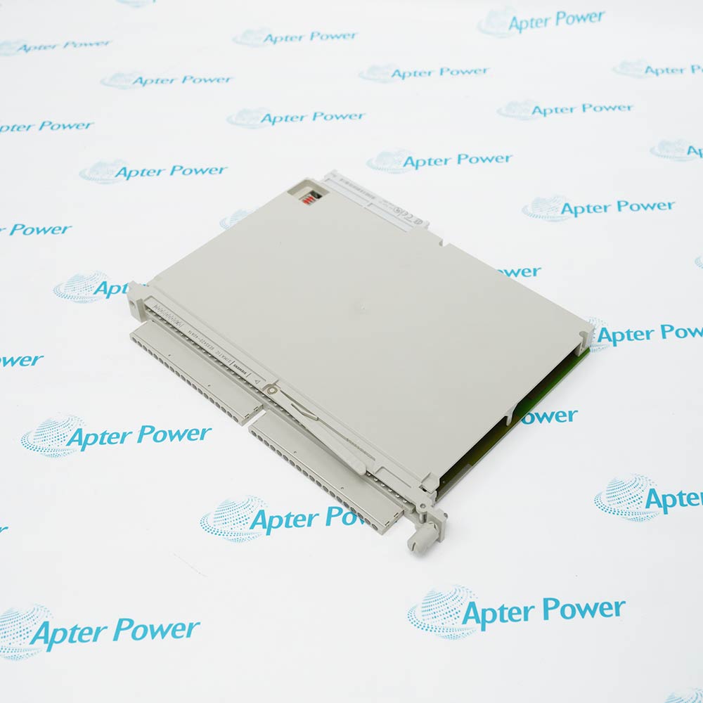
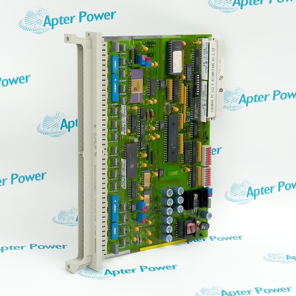
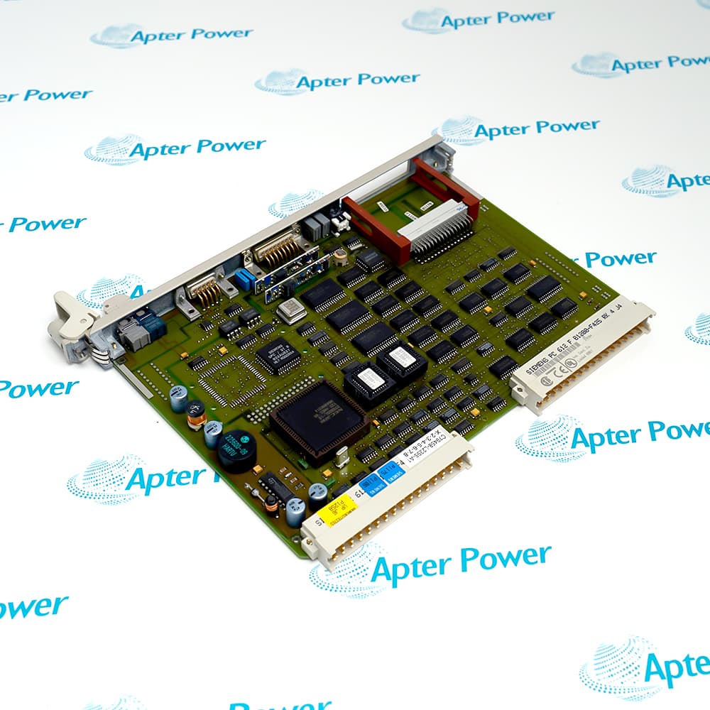
Features:
- Accepts thirty-two non-isolated 24 V DC input signals.
- Uses defined logic thresholds with a typical 3 ms transition delay.
- Requires approximately 30 mA from the 5 V S5 backplane.
The UA14 suffix identifies the lower bus-current version of the S5 420 module. Its electrical data must remain separate from the otherwise similar UA13 execution.
The board provides dense acquisition for sensors and contacts whose states are read cyclically by the legacy controller program.
Maintain the common reference and route long cables according to shielding guidance. Confirm that residual sensor voltage remains below the off-state boundary before commissioning.
6ES5420-4UA14 is sourced by exact suffix to preserve its 30 mA backplane characteristic.
Verified resources for Siemens 6ES5420-4UA14:
Important Notice: Other accessories, manuals, cables, calibration data, software, etc. are not included with this equipment unless listed in the above stock item description. All prices are shown in USD.
- Collect thirty-two standard 24 V field states where S5 rack space is limited.
- Read remote contacts over documented shielded cable distances.
- Maintain the UA14 process-image assignment during legacy line support.
- The 42-pin front interface carries all thirty-two signals and their shared reference.
- Shielded field conductors may extend to the documented 1000 m maximum.
- Unshielded lines are limited to the stated 600 m installation distance.
- Route input cables away from contactor coils and drive output conductors that can induce voltage.
- Keep the common reference stable across the field devices connected to the non-isolated network.
- Include the module's 7 W dissipation when assessing cabinet temperature and airflow.
- Logic 0 is specified up to 5 V while logic 1 begins at 13 V.
- Measure suspect points at the terminal under load to expose leakage or excessive voltage drop.
- Compare the live bit table with the terminal measurement before replacing the module.