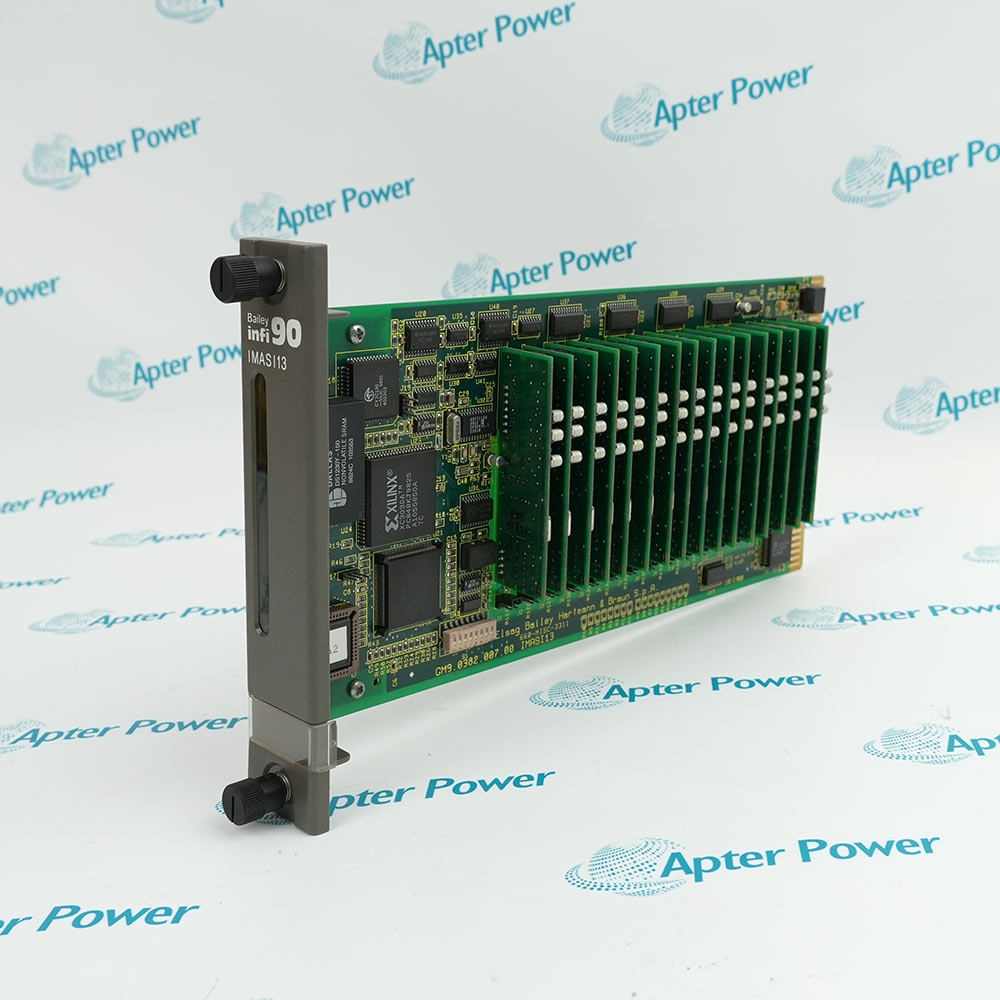
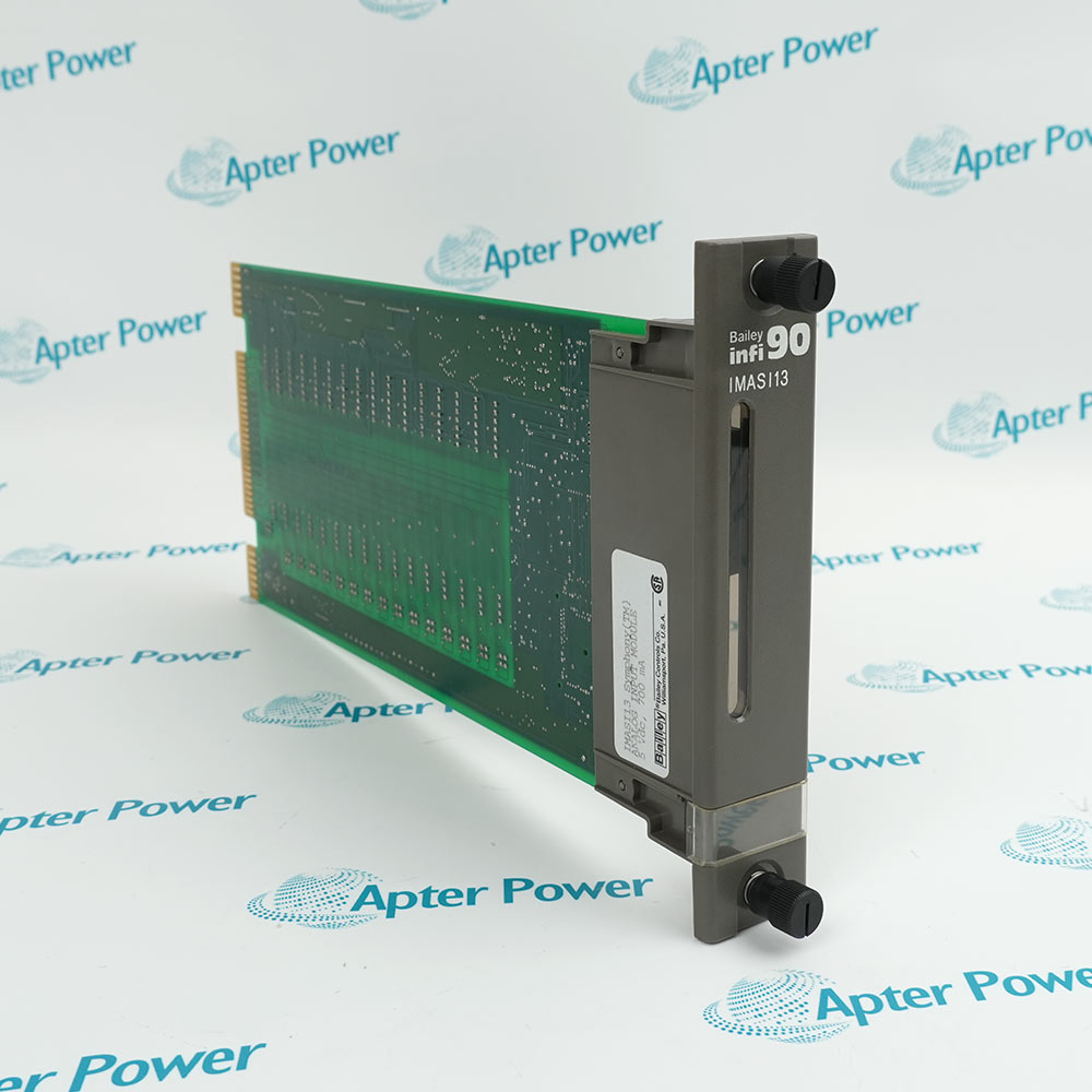
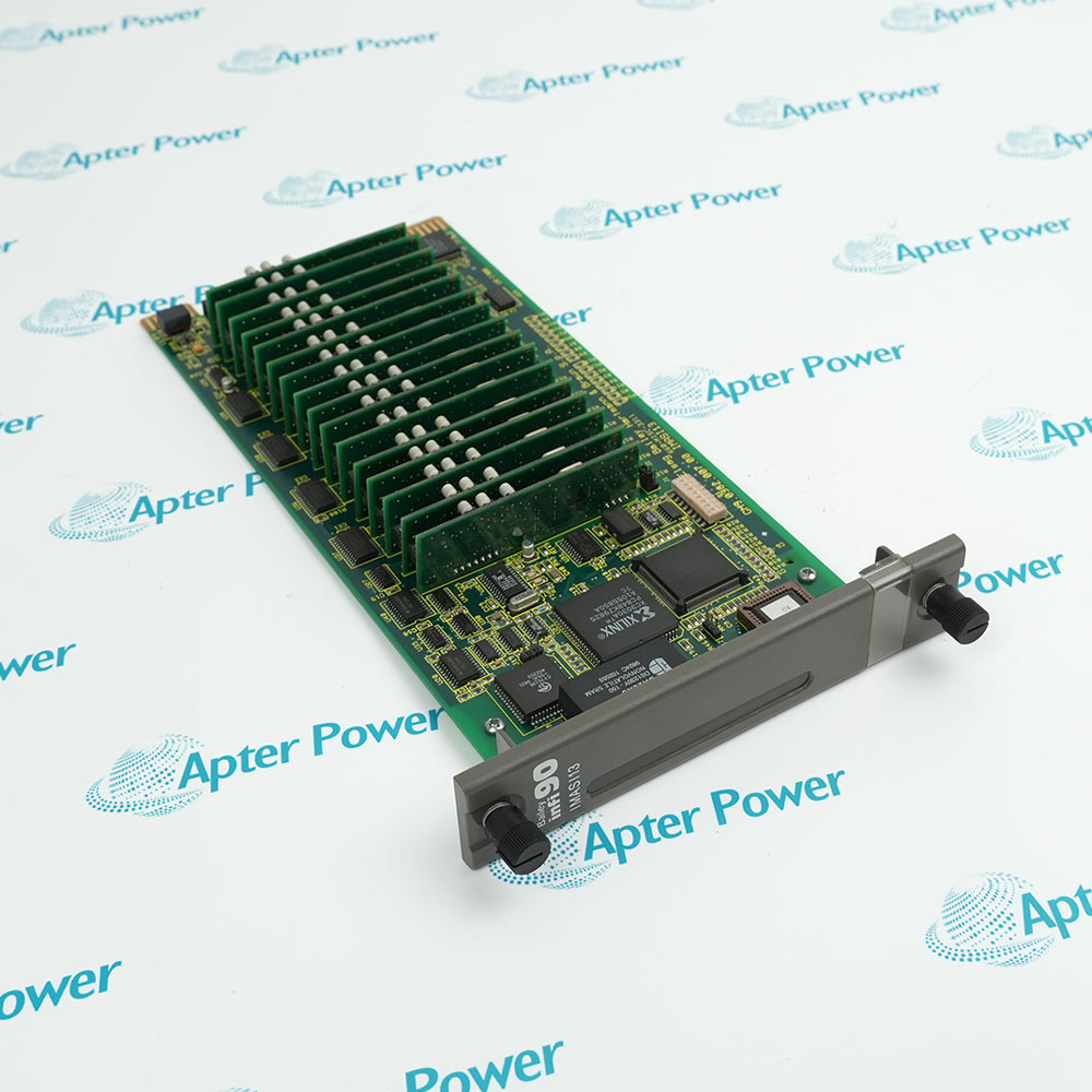
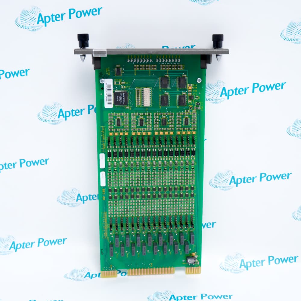
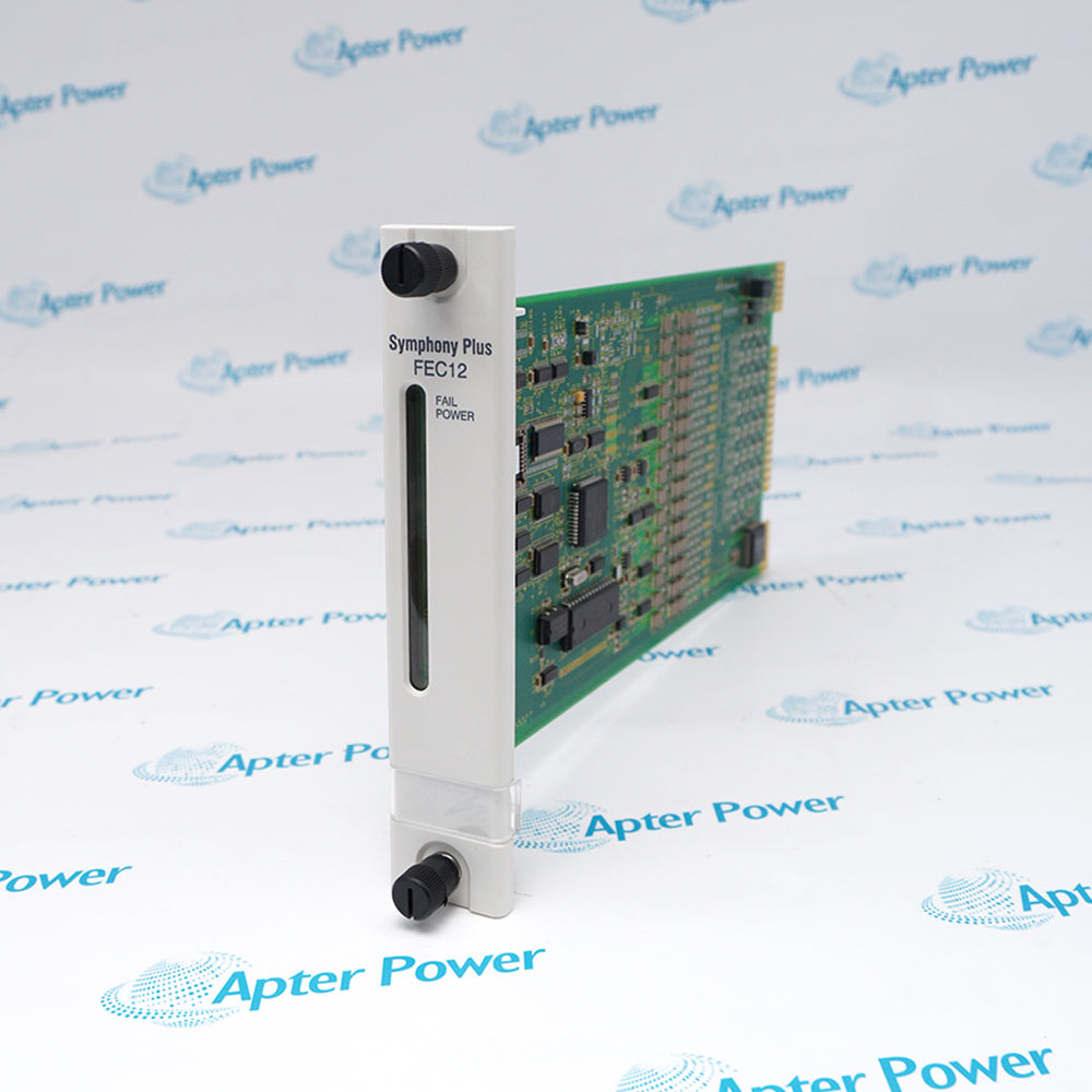
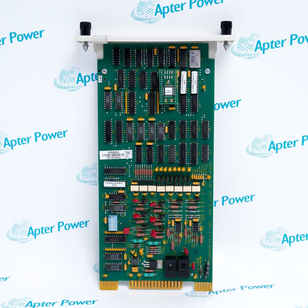
IMASI13
IMASI13
IMASI13
IMASI13
IMASI13
IMASI13
Ask our team:
  • Phone: +86 181 0690 9650
  • E-Mail sales1@apterpower.com
  • Lifecycle status

    Active / Available from OEM
    Apter Power compares loop and termination records, supports official documentation, and verifies condition before shipment.

IMASI13

/ 4.9
1001 reviews | Need a Specific Revision?
Current-loop acquisition for a Harmony rack is concentrated in ABB IMASI13, whose documented termination serves sixteen system-powered two-wire transmitters.
In Stock
Ships by Wednesday, October 28
Fast Shipping Available
Get a quick price for IMASI13
Quantity
*E-mail
Company
*Mobile
*Content
Upload (gif, jpg, jpeg, png, bmp, doc, docx, xls, xlsx, ppt, pdf, csv)

Technical specifications for IMASI13

  • Manufacturer:
    ABB
  • Part Number:
    IMASI13
  • Product Family:
    ABB Bailey
  • Product Type:
    Analog Input Module
  • Stock:
    1
  • Analog input channels:
    16
  • Documented signal:
    4-20 mA
  • Transmitter wiring:
    Two-wire
  • Field power arrangement:
    System powered
  • Termination occupancy:
    2 mounting-unit slots
  • Weight:
    0.45 kg
  • Estimated shipping dimensions:
    3.5 x 31.2 x 17.6 cm
  • Tariff Code:
    Please confirm the destination before shipping
  • Country of origin:
    Sweden
  • Place of shipment:
    Xiamen,Fujian,China
By purchasing this item, you agree to the Terms & Conditions, ApterPower is not an authorized distributor for listed manufacturers or tradenames and therefore the manufacturer's warranty does not apply. All our products come with ApterPower's 1-year warranty.

More Information

Overview Manuals Specifications Loop Polarity System Power Loop Handover

Features:

  • Sixteen analog inputs for two-wire 4-20 mA devices
  • System-powered field-loop termination arrangement
  • Two mounting-unit slots allocated to the documented termination device
IMASI13 gathers a full sixteen-loop current-input set through one Harmony rack termination path.

System power and the two-wire transmitter arrangement make polarity and loop continuity central commissioning evidence.

The rack position, termination assembly, scaling, and calibration history should move together with any spare decision.

Availability of IMASI13 is subject to Apter Power's current inventory and sourcing confirmation.
IMASI13 Analog Input Module Manuals, Datasheets, Links Important Notice: Other accessories, manuals, cables, calibration data, software, etc. are not included with this equipment unless listed in the above stock item description. All prices are shown in USD.
IMASI13 Analog Input Module Specs

General

  • ManufacturerABB
  • ModelIMASI13
  • ConditionNew Original ready stock
  • Product FamilyHarmony Rack I/O
Important Notice: Other accessories, manuals, cables, calibration data, software, etc. are not included with this equipment unless listed in the above stock item description. All prices are shown in USD.

Two-wire transmitter path

  • Positive path: retain the approved supply-to-transmitter route.
  • Return path: reconcile every channel with the terminal schedule.
  • Shield: preserve the site grounding convention.
  • Isolation: de-energize and identify conductors before transfer.

Termination power evidence

  • Source: document the system-powered loop arrangement.
  • Occupancy: reserve the two required mounting-unit slots.
  • Distribution: trace common power and protection points.
  • Baseline: record loop current before shutdown.

Analog acceptance sequence

  • Identity: match all sixteen loop tags to controller points.
  • Current: inject or measure approved 4-20 mA values.
  • Scaling: compare engineering units with the controller display.
  • Record: retain as-left values and channel status.
Description
The termination design around IMASI13 establishes sixteen analog input positions for two-wire 4-20 mA field devices. ABB documents a system-powered termination arrangement occupying two mounting-unit slots for this signal path.

Loop engineering gives IMASI13 its practical value in Harmony rack I/O: each transmitter circuit must retain the correct polarity, shield, channel identity, field reference, and controller scaling from the installed design rather than inherit assumptions from a neighboring analog module.

Before commissioning IMASI13, reconcile the complete module label, rack location, termination assembly, sixteen-loop schedule, power distribution, and calibration records. A source type outside the documented two-wire current-loop arrangement requires separate official evidence before connection.
Alternative Names
IMASI 13 IMASI-13 ABB Bailey IMASI13 Harmony IMASI13 YIMASI13 sixteen-channel two-wire analog input module
Technical notes
Confirm that every IMASI13 channel is a documented two-wire 4-20 mA loop using the system-powered termination arrangement. The official termination device occupies two mounting-unit slots for sixteen inputs; preserve loop polarity, channel scaling, shield practice, field references, and the installed terminal schedule before moving any transmitter conductor.
Exceptional Service

Our Mission

  • 100% Satisfaction

    We believe expertise is priceless. With over 20 years of experience, and top engineers on staff, we can help you solve or avoid problems that threaten your business.
  • Trust Guaranteed

    Not only do we have a vast inventory, our team makes sure every piece of equipment is in working condition. Your purchases are also backed by our Warranty.
  • Expertise

    Time is money, especially when your equipment is down. We work quickly to get your equipment on its way so you can get it back up and running.

FAQS

The following is a list of questions commonly asked by our customers. Please contact us if you have a question about our process that is not answered below.
Why must an IMASI13 project confirm two-wire transmitter service before connection?
ABB documents the relevant termination for sixteen 4-20 mA two-wire inputs, so a different sensor or wiring method needs separate manufacturer evidence.
How does the system-powered termination arrangement affect IMASI13 outage planning?
Preserve the shared power distribution, protection, polarity, and common terminal path; isolating one loop can affect how the rack termination is worked safely.
Which cabinet-space detail belongs in an IMASI13 replacement review?
The documented termination device occupies two mounting-unit slots, so the retained cabinet layout and terminal assembly must be verified before hardware is moved.
When an IMASI13 channel reads low, what diagnostic order protects the loop evidence?
Check transmitter power, loop current, polarity, terminal continuity, shield practice, channel scaling, and controller indication before changing the module.
What should be retained before the sixteen loops on IMASI13 are disconnected?
Save the loop schedule, terminal numbers, conductor tags, calibration ranges, current readings, rack position, and photographs of the termination assembly.
Which information makes an IMASI13 quotation specific to the installed system?
Provide the complete label, quantity, rack and termination photographs, two-wire loop count, system-power details, destination, and required outage date.

Product Browsing History