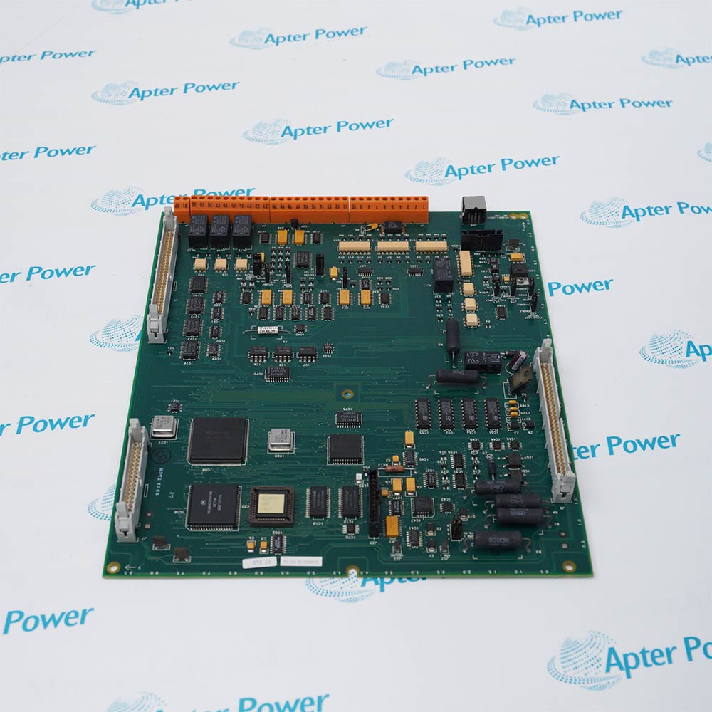
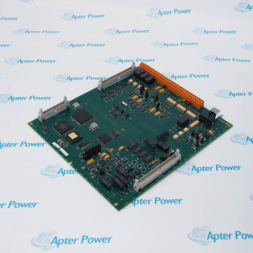
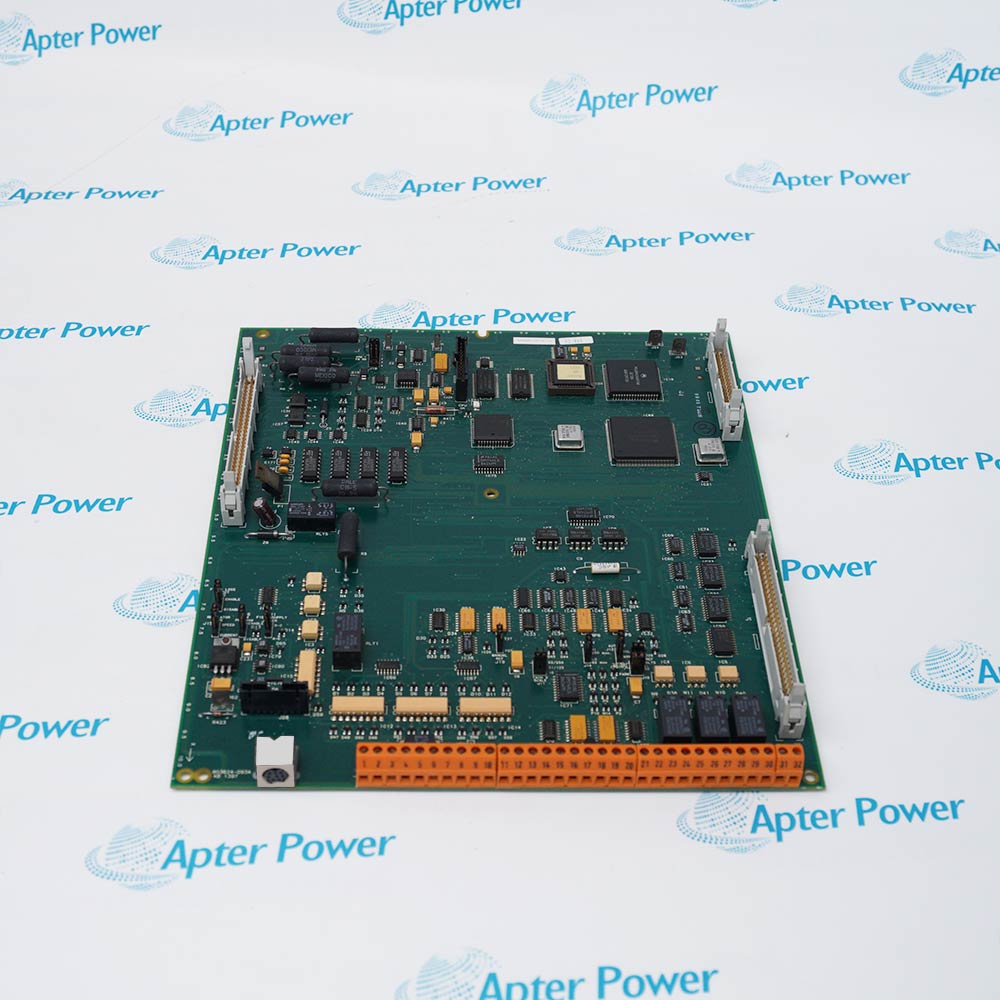
AB 803624-093A
AB 803624-093A
AB 803624-093A
AB 803624-093A
AB 803624-093A
AB 803624-093A
Ask our team:
  • Phone: +86 181 0690 9650
  • E-Mail sales1@apterpower.com

803624-093A

/ 4.9
1001 reviews | Need a Specific Revision?
Allen-Bradley 803624-093A is a regulator board used to configure speed or current regulation and analog feedback functions in Bulletin 1397 DC drives.
In Stock
Ships by Wednesday, October 28
Fast Shipping Available
Get a quick price for 803624-093A
Quantity
*E-mail
Company
*Mobile
*Content
Upload (gif, jpg, jpeg, png, bmp, doc, docx, xls, xlsx, ppt, pdf, csv)

Technical specifications for 803624-093A

  • Manufacturer:
    Allen-Bradley
  • Part Number:
    803624-093A
  • Product Family:
    Allen Bradley Drives
  • Product Type:
    1397 DC Drive Regulator Board
  • Stock:
    1
  • Regulator Mode Selection:
    J15 selects speed regulation or current regulation
  • Field-Loss Detection:
    J20 enables or disables field-loss detection
  • Field Supply Selection:
    J21 selects the standard or optional enhanced field-supply arrangement
  • Manual Reference Selection:
    J19 selects the internal manual-reference potentiometer or an external source
  • Tachometer Range:
    J14 selects 62 V maximum or 250 V maximum
  • Tachometer Scale:
    J11 provides 62/250, 31/125, and 16 V-per-1000-rpm ranges
  • Analog Reference:
    J10 and J12 configure voltage or current reference operation
  • Field Wiring:
    32-position terminal strip documented for the regulator board
  • Tariff Code:
    3926909090
  • Country of origin:
    USA
  • Place of shipment:
    Xiamen, Fujian, China
By purchasing this item, you agree to the Terms & Conditions, ApterPower is not an authorized distributor for listed manufacturers or tradenames and therefore the manufacturer's warranty does not apply. All our products come with ApterPower's 1-year warranty.

More Information

Overview Manuals Feedback References Field Control Application
  • Jumper-selectable speed or current regulation
  • Configurable tachometer range and analog-reference input
  • Field-loss, field-supply, and manual-reference selections

803624-093A is an Allen-Bradley 1397 DC Drive Regulator Board designed for the Bulletin 1397 DC drive regulator assembly.

Its power-up configuration determines how the 1397 drive interprets feedback and references, making the original jumper map essential replacement information.

Before installation or replacement, record every regulator-board jumper and verify feedback polarity, terminal-strip wiring, and field-control options before power is applied.

Availability, condition, price, and shipping time for 803624-093A are confirmed during quotation.

Allen-Bradley 803624-093A 1397 DC Drive Regulator Board Manuals, Datasheets, Links

Important Notice: Other accessories, manuals, cables, calibration data, software, etc. are not included with this equipment unless listed in the above stock item description. All prices are shown in USD.

  • Select the documented tachometer voltage range with J14
  • Match J11 tachometer scaling to the installed feedback device
  • Verify tachometer polarity and wiring before a loaded run
  • Configure J10 and J12 for the installed voltage or current reference
  • Use J19 to select the internal manual potentiometer or external source
  • Confirm reference polarity and zero command before enabling the drive
  • Match J21 to the standard or enhanced field-supply arrangement
  • Set J20 only after identifying the installed field-control option
  • Provide external field-loss detection when the documented configuration requires it
  • Variable-speed industrial DC motor control
  • Regenerative DC drive systems using Bulletin 1397 hardware
  • Machine-drive applications requiring tachometer or analog-reference regulation
Description
803624-093A is an Allen-Bradley 1397 DC Drive Regulator Board for the Bulletin 1397 DC drive regulator assembly.

The board provides jumper-selectable regulator mode, tachometer range and scaling, analog reference selection, field-loss handling, and manual-reference routing.

Before installation or replacement, confirm the 803624-093A nameplate, all jumper positions, the feedback source, analog-reference type, field-supply arrangement, and terminal-strip wiring.
Alternative Names
803624-093A Allen-Bradley 803624-093A Rockwell Automation 803624-093A 803624093A 1397 803624-093A Bulletin 1397 803624-093A
Technical notes
803624-093A requires the original regulator-mode, tachometer, reference, and field-supply jumper selections; an incorrect configuration can cause loss of feedback, wrong direction, or overspeed.
Exceptional Service

Our Mission

  • 100% Satisfaction

    We believe expertise is priceless. With over 20 years of experience, and top engineers on staff, we can help you solve or avoid problems that threaten your business.
  • Trust Guaranteed

    Not only do we have a vast inventory, our team makes sure every piece of equipment is in working condition. Your purchases are also backed by our Warranty.
  • Expertise

    Time is money, especially when your equipment is down. We work quickly to get your equipment on its way so you can get it back up and running.

FAQS

The following is a list of questions commonly asked by our customers. Please contact us if you have a question about our process that is not answered below.
Can Allen-Bradley 803624-093A be installed without recording the original jumper positions?
No. The regulator reads key jumper selections at power-up, so copy J10, J11, J12, J14, J15, J19, J20, and J21 before removing the original board.
What is the main compatibility risk when replacing Allen-Bradley 803624-093A?
The greatest risk is restoring the wrong regulator mode or feedback/reference range. Match the drive application, tachometer source, field supply, and analog reference before energizing the drive.
Does Allen-Bradley 803624-093A use the same field-loss setting with every field-control option?
No. Rockwell notes that the J20 selection is ignored with the field-current regulator option; an external detection method is required if field-loss detection is disabled.
Can Allen-Bradley 803624-093A use an external manual speed reference?
Yes. J19 routes manual reference either from the board potentiometer or an external source, so the installed wiring and intended operating mode must agree with the jumper.
Why might a drive overspeed after fitting Allen-Bradley 803624-093A?
An incorrect tachometer voltage range, tachometer scale, polarity, or feedback wiring can produce the wrong speed feedback. Verify those selections before uncoupled test operation.
What records should a maintenance team keep for Allen-Bradley 803624-093A?
Keep the board label, complete drive catalog, photographed jumper map, tachometer type and polarity, reference source, field-control arrangement, and terminal wiring record. These details prevent a replacement from inheriting an unsafe or incorrect configuration.
What should be tested after installing Allen-Bradley 803624-093A?
Check field establishment, reference polarity, zero-speed behavior, tachometer feedback, current limiting, and controlled acceleration before reconnecting the production load.