Features:
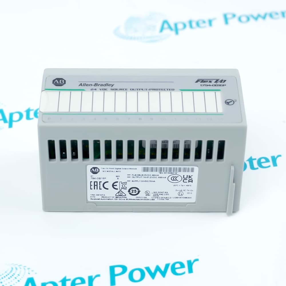
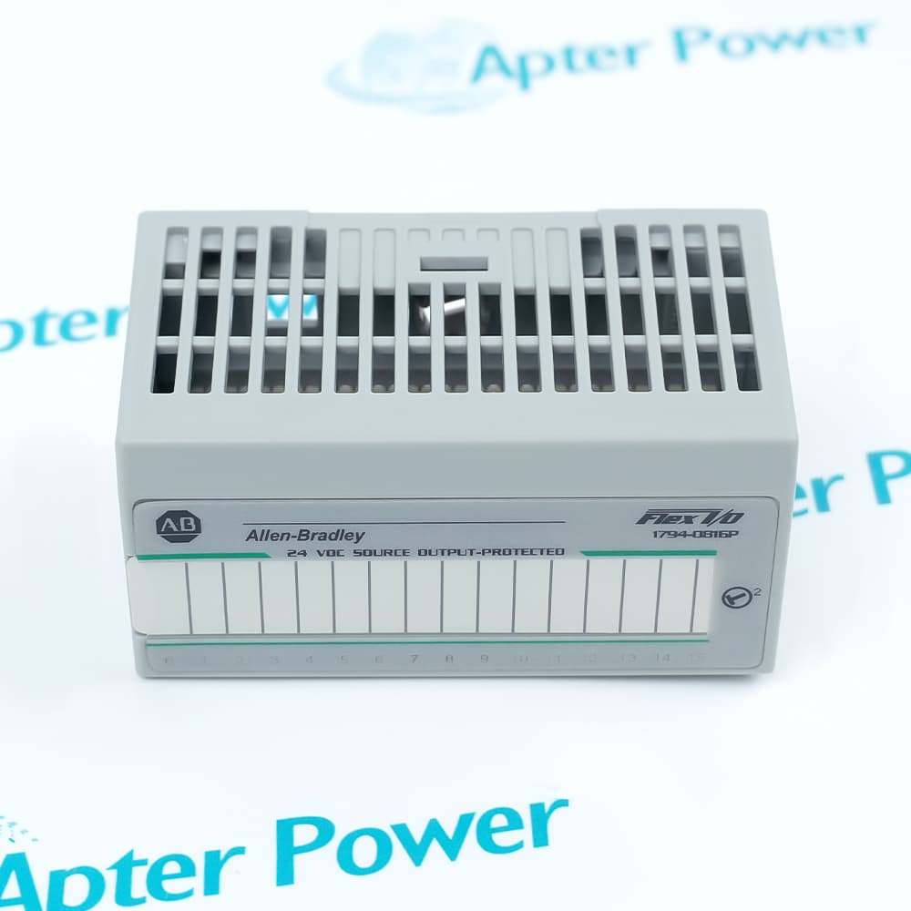
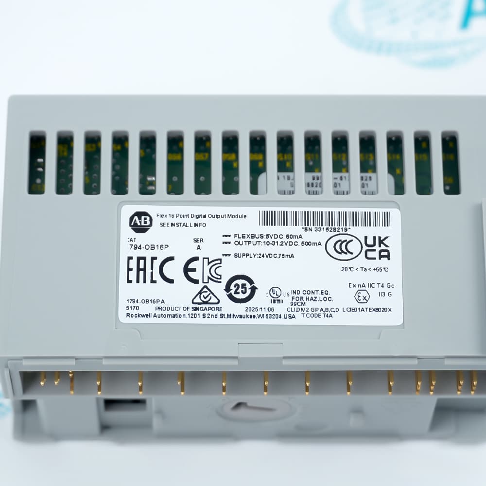
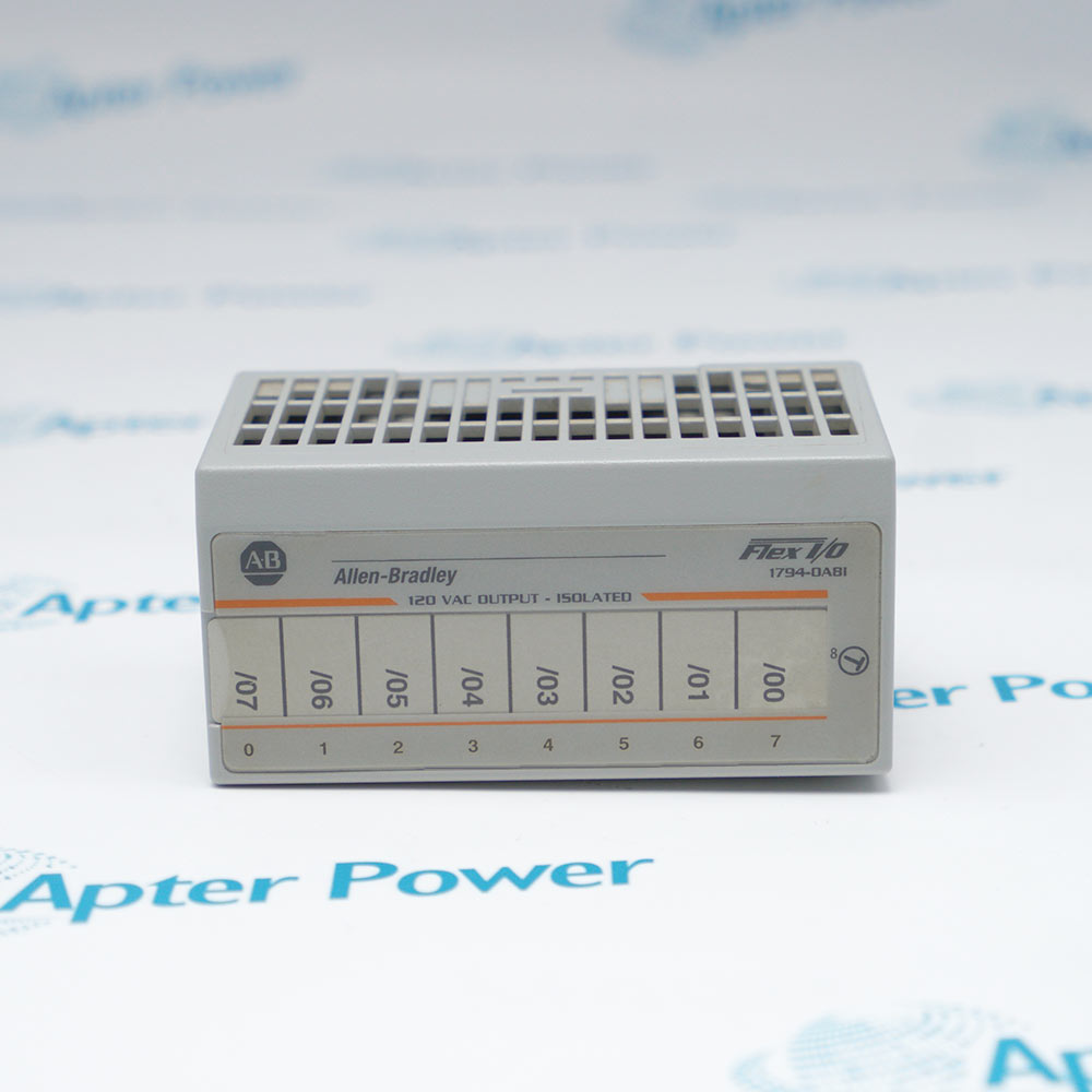
- Allen-Bradley 1794-OB16P places sixteen protected sourcing outputs at a FLEX I/O station.
- The output image controls 24 V DC field loads through the module's electronic switching stage.
- Sixteen yellow indicators show the commanded state of the individual output points.
FLEXBUS supplies the module logic while a separate field source provides energy for the connected loads.
Electronic protection acts at the output stage and limits the effect of overload or short-circuit conditions.
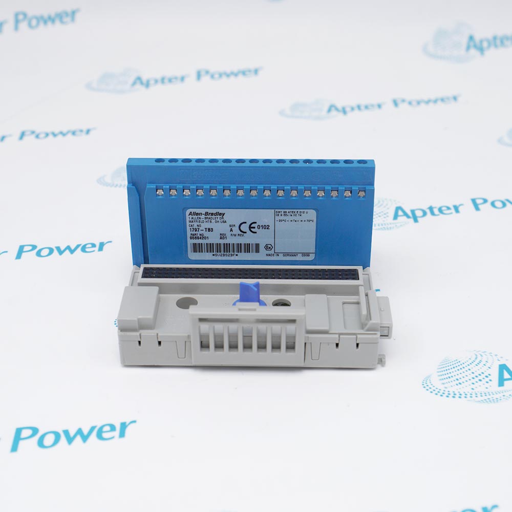
A compatible terminal base retains supply, common and output conductors beneath the removable electronics.
The Allen-Bradley 1794-OB16P FLEX I/O Output Module may still be available for purchase and support from Apter Power beyond End-Of-Life (EOL) by the manufacturer (OEM).
Allen-Bradley 1794-OB16P FLEX I/O Output Module Manuals,Datasheets,Link
Important Notice: Other accessories, manuals, cables, calibration data, software, etc. are not included with this equipment unless listed in the above stock item description. All prices are shown in USD.
Driving a DC load from the FLEX I/O image
- Adapter command: Each image-table bit represents one of the sixteen output points.
- Sourcing stage: An active channel connects positive field power toward its assigned load.
- Return path: Load current completes through the DC common on the terminal base.
- Point indication: A yellow indicator follows the commanded state for local checking.
Containing an overloaded output point
- Electronic limit: A protected channel restricts fault energy when excessive current is detected.
- Fault removal: The overload or short circuit must be cleared before normal switching resumes.
- Surge boundary: The short pulse allowance is separate from the continuous-current rating.
- Thermal total: Point loading must remain within the complete module current and dissipation limits.
Keeping permanent wiring below the removable module
- Compatible bases: Supported 1794 terminal bases carry output, supply and common conductors.
- Removable electronics: Module replacement leaves terminated field wires on the base.
- Keyswitch: Position 2 helps prevent an incompatible FLEX I/O module from occupying the base.
- Power distribution: Field-source capacity and conductor grouping must cover every energized load.
Relating controller bits to physical outputs
- Sixteen-bit map: Image positions 0 through 15 align with physical points 0 through 15.
- Cyclic transfer: The communication adapter moves the controller image into the module over FLEXBUS.
- Switching response: The field stage changes after its OFF-to-ON or ON-to-OFF interval.
- State comparison: Controller command, point indicator and load voltage should agree during checks.