Features:
- Bachmann ME203/CN combines a 33 MHz Intel 80386 EX processor with dedicated controller memory.
- Separate serial and CAN/CANopen interfaces divide the module's communication traffic.
- A 17 W I/O supply and PC Card storage share the single-width M1 module.
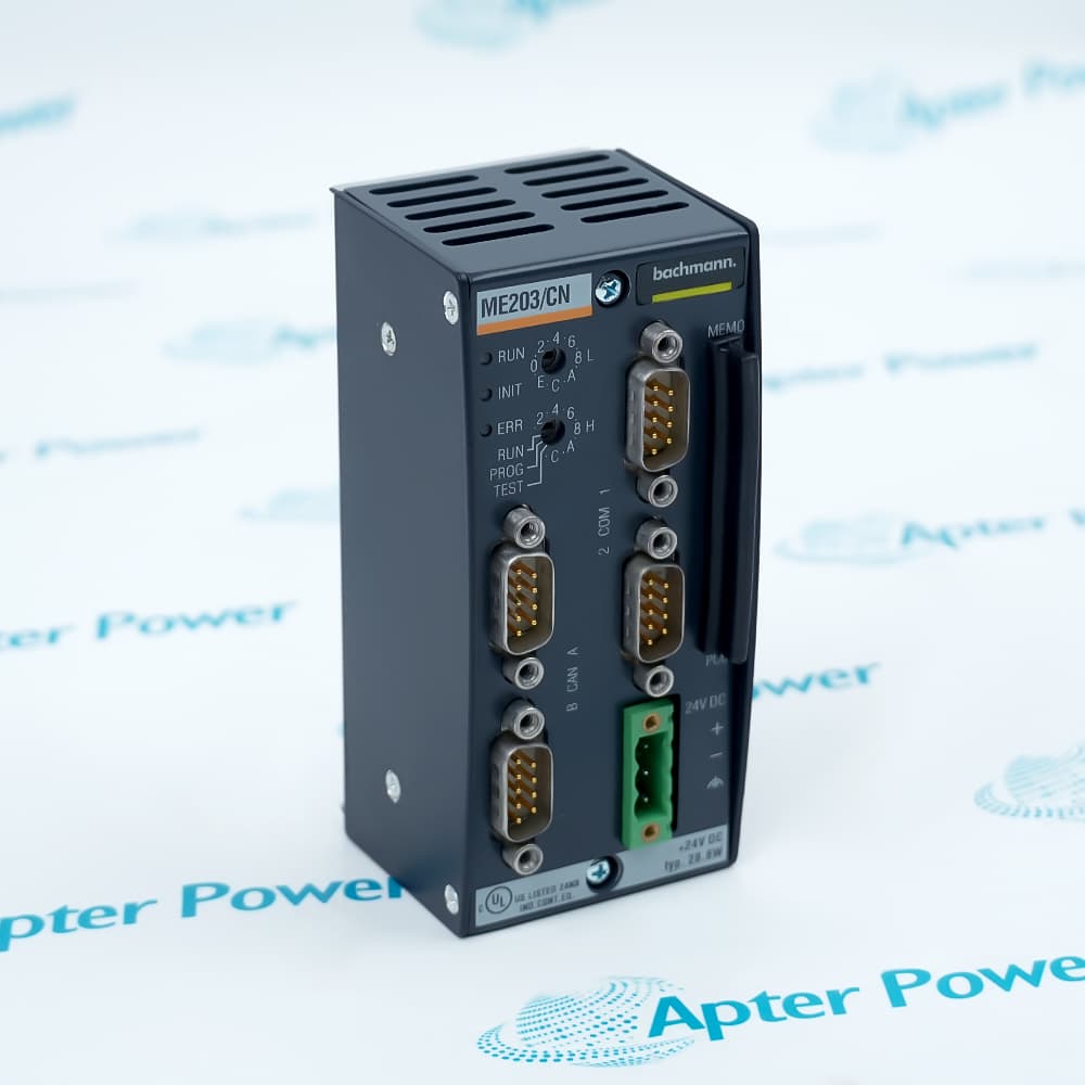
Bachmann ME203/CN places controller processing and local communication resources in one M1 module.
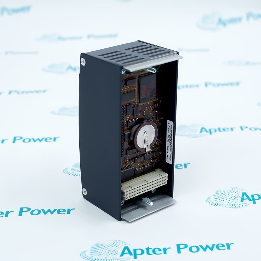
Its memory areas separate running data, retained values, boot code and program or file storage.
Serial devices and CAN/CANopen nodes connect through dedicated interfaces instead of sharing one physical port.
The Bachmann ME203/CN M1 Processor Module may still be available for purchase and support from Apter Power beyond End-Of-Life (EOL) by the manufacturer (OEM).
Bachmann ME203/CN M1 Processor Module Manuals,Datasheets,Link
Important Notice: Other accessories, manuals, cables, calibration data, software, etc. are not included with this equipment unless listed in the above stock item description. All prices are shown in USD.
How the onboard ports divide traffic
- Fixed serial path: One RS232 interface provides a dedicated point-to-point connection.
- Configurable path: The second port selects RS232, RS422 or RS485 signaling and uses a 64-byte FIFO.
- Fieldbus path: A separate CAN interface carries CAN or CANopen communication.
- Port separation: Choosing a serial mode does not replace the independent CAN channel.
Where controller data is held
- Working area: DRAM supplies the main execution space for processor operations.
- Retained area: Battery-backed SRAM preserves values across normal power removal.
- Internal flash: Boot flash remains separate from program and file storage.
- Removable storage: The PCC201/xx slot adds a PC Card without replacing the processor module.
Controller and I/O power relationship
- Incoming supply: The 24 V DC input feeds the module across its documented operating range.
- Local conversion: The integrated supply generates regulated rails for the attached I/O load.
- Load budget: The three output rails share the documented 17 W I/O supply capacity.
- Isolation boundary: A 500 V barrier separates the incoming supply from system electronics.
How the processor reports and identifies state
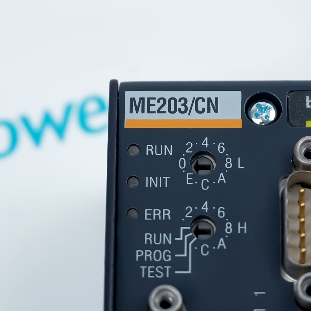
- RUN indication: The RUN LED identifies the processor's normal execution state.
- Initialization: INIT distinguishes startup activity from normal running.
- Error indication: ERROR provides a dedicated visual state for processor faults.
- CPU identity: Rotary hexadecimal switches assign the controller identifier without editing the program.