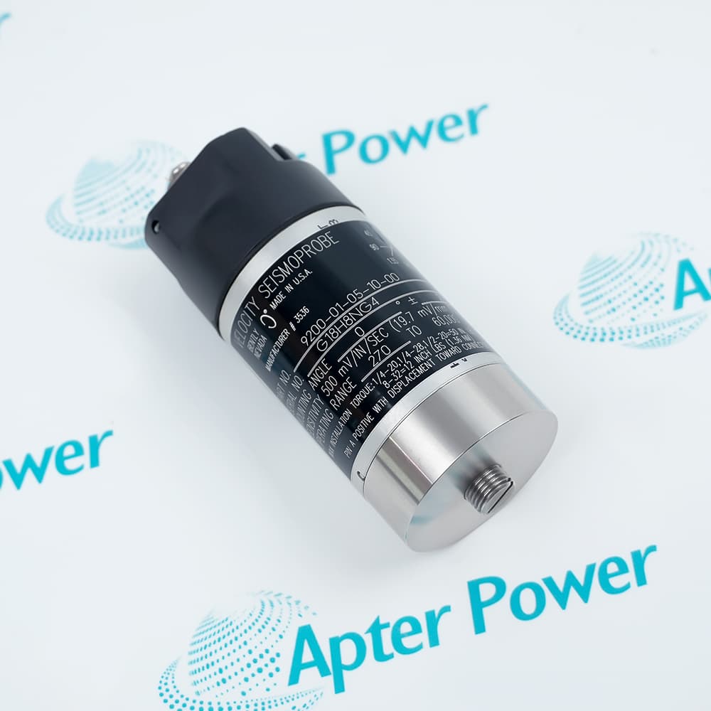
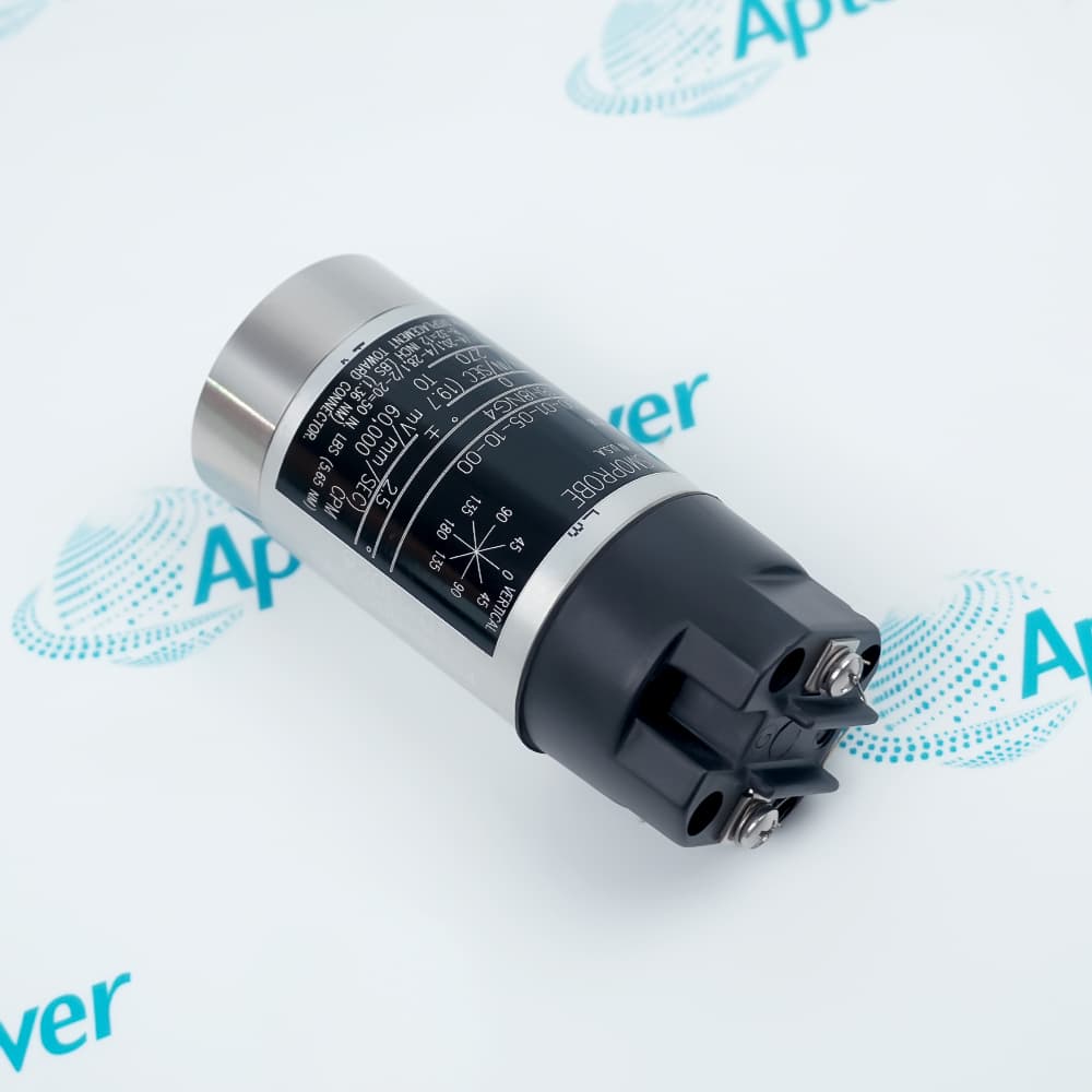
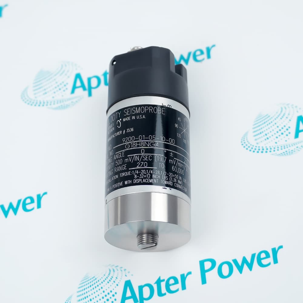
Features:
- Generates a velocity-proportional signal without external power
- Uses the 01 low-frequency orientation option
- Combines a terminal block with an M10 × 1 mounting base
Bently Nevada 9200-01-05-10-00 measures absolute motion of a casing, bearing housing or structure through a moving-coil mechanism.
Its response depends on the specified mounting orientation, mechanical coupling and electrical load, so installation details directly influence the usable signal.
The complete code identifies a top terminal block, circular M10 × 1 stud base and no-agency-approval configuration.
The Bently Nevada 9200-01-05-10-00 Seismoprobe Velocity Transducer may still be available for purchase and support from Apter Power beyond End-Of-Life (EOL) by the manufacturer (OEM).
Bently Nevada 9200-01-05-10-00 Seismoprobe Velocity Transducer Manuals,Datasheets,Link
Important Notice: Other accessories, manuals, cables, calibration data, software, etc. are not included with this equipment unless listed in the above stock item description. All prices are shown in USD.
How the Seismoprobe produces its signal
- Mechanical motion: Relative motion between the internal coil and magnet follows case vibration along the sensing axis.
- Generated voltage: The moving-coil mechanism produces a voltage proportional to vibration velocity.
- No excitation: The transducer does not require an external sensor power supply.
- Polarity: Motion toward the connector makes terminal A positive relative to terminal B.
Orientation and mounting control the low-frequency response
- Angle code: Option 01 is calibrated for installation at 0 ±2.5 degrees.
- Mounting surface: A rigid, flat machine surface preserves the intended mechanical coupling.
- Stud connection: The 10 base uses the circular M10 × 1 stud arrangement.
- Torque control: Applying the documented mounting torque avoids a loose joint or damaged base.
The connected circuit shapes the measured response
- Calibration load: Sensitivity is specified with a 10 kΩ load across terminals A and B.
- Coil impedance: The coil resistance and inductance form part of the electrical source behavior.
- Cable length: Long interconnection cable adds capacitance and changes high-frequency roll-off.
- Input check: The receiving instrument should present the expected load before sensitivity is evaluated.
Connector and approval codes define this build
- Top terminal block: Code 05 provides terminals on the top of the transducer for field wiring.
- Cable exclusion: No integral cable is supplied with the 05 connection option.
- Mounting code: Code 10 selects the circular base with an M10 × 1 stud.
- Approval code: Final code 00 specifies no agency approval for this configuration.