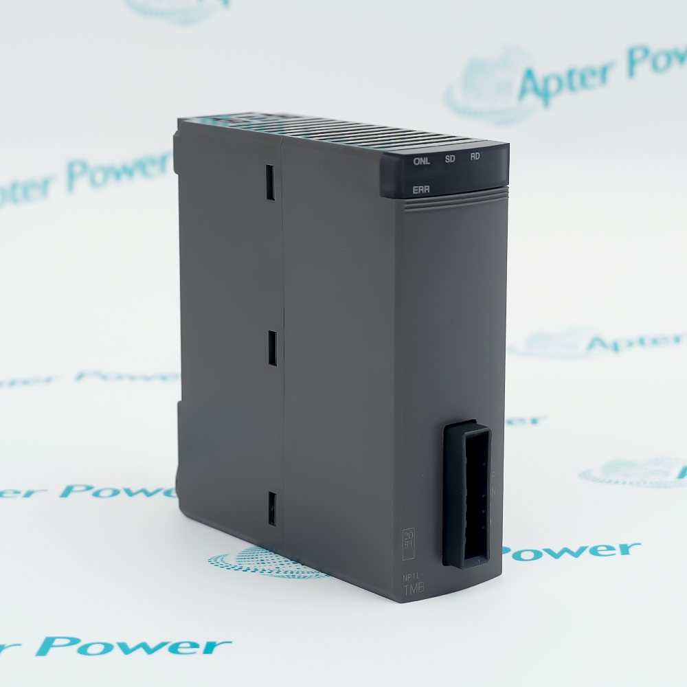
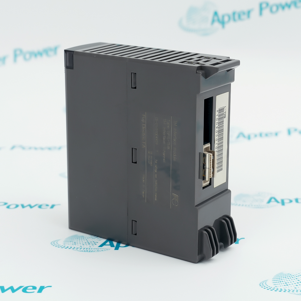
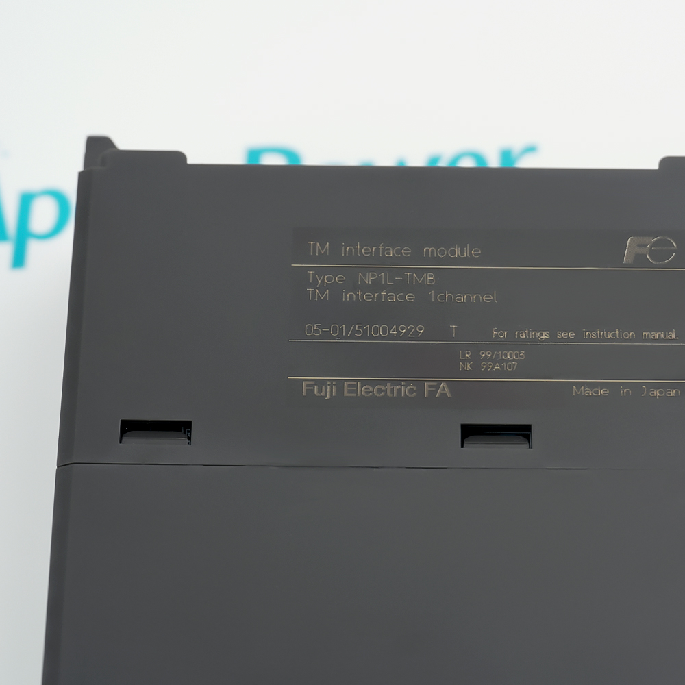
Features:
- Marked type: Fuji Electric FA identifies the offered hardware as NP1L-TMB, the exact code needed for an exact-part request.
- Interface role: The manufacturer label calls it a TM interface module, distinguishing it from a differently named NP1L network card.
- Channel identity: The nameplate specifies one TM interface channel, relevant when comparing the installed connection arrangement.
The marked model and TM-channel role provide the clearest starting point for identifying this spare in an existing controller.
A shared NP1L prefix does not make another interface card the same module; the installed type and host drawing remain useful when planning a replacement.
The one-channel marking helps distinguish this module when several Fuji interface cards are installed in the same cabinet.
Apter Power can compare the installed NP1L-TMB marking and host-system details and provide an exact-part quotation.
Fuji Electric NP1L-TMB TM Interface Module Manuals,Datasheets,Link
Important Notice: Other accessories, manuals, cables, calibration data, software, etc. are not included with this equipment unless listed in the above stock item description. All prices are shown in USD.
- Exact model: The installed unit should carry NP1L-TMB, since another NP1L interface type may serve a different connection role.
- TM channel: The marked one-channel interface should be compared with the channel shown on the host-system drawing.
- Offered scope: Photographs of the existing module and mating connection help Apter Power distinguish the needed card from cables or other adjacent parts.
- System link: In Terasaki GAC21, the NP1L-TMB connects the SX-bus controller to the TM monitor link, so the installed system must use that route.
- Transmission range: The GAC21 manual specifies 2–5 kbps for this TM interface; match the existing monitor-link design rather than assuming another PLC port is equivalent.
- Cable run: The documented TM connection uses a seven-core cable with a maximum 2 km transmission distance; check the installed route before replacing the module.
- Mating connector: The manual identifies a six-pin dynamic connector, making the installed plug part of the replacement-fit check.
- Normal indication: The GAC21 manual shows ONL on and ERR off during normal NP1L-TMB operation, providing a first local status check.
- Transmission activity: A blinking SD indicator denotes data output from the TM interface, helping distinguish an active transmit path from an idle one.
- Reception activity: A blinking RD indicator denotes incoming data, so it should be interpreted separately from SD when tracing a monitor-link fault.
- Fault pattern: ERR on with ONL off is documented as a fatal fault; ERR and ONL both on indicate a nonfatal fault, requiring different troubleshooting paths.
- GAC21 controller: Terasaki specifies NP1L-TMB as the TM interface in its GAC21 generating-plant management controller, rather than as a standalone field I/O card.
- Ship-monitor output: In that controller, the module carries alarm and display output to the ship monitor; the application is the documented marine monitoring path.
- Warning transmission: The GAC21 communication section routes warning signals to the Terasaki Monitor System over TM multiplex, giving this module a defined monitor-link role.