Ask our team:
  • Phone: +86 181 0690 9650
  • E-Mail sales1@apterpower.com
  • Lifecycle status

    Discontinued / Obsolete by OEM
    When sourcing DS200DTBDG1A, Apter Power can prepare quotation information, supply related manufacturer documents, and investigate whether an official replacement reference exists.

DS200DTBDG1A

/ 4.9
1001 reviews | Need a Specific Revision?
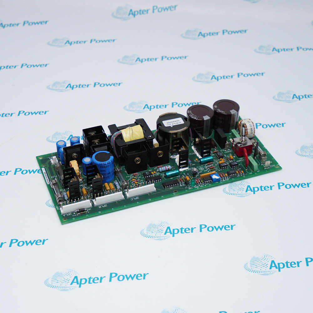
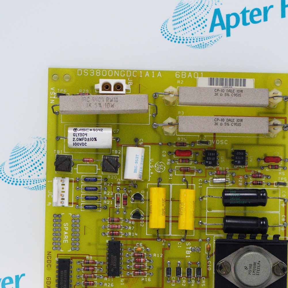
General Electric DS200DTBDG1A is a Mark V LM contact output expansion termination module that interfaces 30 TCRA relay outputs with field contact, solenoid, and selected ignition-transformer circuits.
In Stock
Ships by Thursday, October 29
Fast Shipping Available
Get a quick price for DS200DTBDG1A
Quantity
*E-mail
Company
*Mobile
*Content
Upload (gif, jpg, jpeg, png, bmp, doc, docx, xls, xlsx, ppt, pdf, csv)

Technical specifications for DS200DTBDG1A

  • Manufacturer:
    General Electric
  • Part Number:
    DS200DTBDG1A
  • Product Family:
    GE Mark V/VI Driver Board
  • Product Type:
    Contact Output Expansion Termination Module
  • Stock:
    1
  • Control Platform:
    Mark V LM SPEEDTRONIC
  • Core Locations:
    , , and
  • Relay Source:
    30 relays from TCRA location 5
  • Relay Signal Paths:
    JS1 through JS8
  • Solenoid Outputs:
    Contact outputs 31 through 46
  • Solenoid Power:
    J8 from TCPD
  • Ignition Outputs:
    47 and 48 via J19/J20
  • Tariff Code:
    8538900000
  • Country of origin:
    USA
  • Place of shipment:
    Xiamen,Fujian,China
By purchasing this item, you agree to the Terms & Conditions, ApterPower is not an authorized distributor for listed manufacturers or tradenames and therefore the manufacturer's warranty does not apply. All our products come with ApterPower's 1-year warranty.

More Information

Overview Manuals Relay Paths Solenoid Setup Ignition Output Checks

Features:

  • Terminates 30 relay outputs from the TCRA board in location five of a digital core.
  • Supports dry-contact or powered-solenoid use for outputs 31 through 46.
  • Provides an ignition-transformer option for outputs 47 and 48.
DS200DTBDG1A is a contact output expansion termination module used in the Q11, Q21, and Q51 Mark V LM digital cores. It is an output board, not a contact-input termination module.

JS1 through JS8 carry relay signals from TCRA. J8 supplies the separate solenoid-power path from TCPD.

Paired P/M jumpers configure outputs 31-46, while J19 and J20 participate in the optional ignition-transformer path for outputs 47 and 48.

For installations retaining the General Electric DS200DTBDG1A Contact Output Expansion Termination Module, Apter Power offers post-EOL purchasing and documentation support.
General Electric DS200DTBDG1A Contact Output Expansion Termination Module Manuals, Datasheets, Links Important Notice: Other accessories, manuals, cables, calibration data, software, etc. are not included with this equipment unless listed in the above stock item description. All prices are shown in USD.
  • Relay interface: DS200DTBDG1A connects to the 30 relays on the TCRA board in location five of the Q11, Q21, or Q51 core. JS1 through JS8 divide those relay signals into defined cable groups.
  • Grouped symptom: A symptom affecting several outputs in one group can therefore follow a common JS connector even when other DTBD outputs operate normally.
  • Command-versus-power test: The TCRA relay command and the field-power path should be tested separately because the relay state alone does not prove that solenoid voltage is present.
  • Configured outputs: Sixteen DTBD outputs can be configured for solenoid service. P1/M1 through P16/M16 correspond to outputs 31 through 46.
  • Paired jumpers: Each Pn/Mn pair must be both installed or both removed. Mixed positions do not represent a valid powered-output or dry-contact configuration.
  • Solenoid supply: J8 receives the solenoid supply from TCPD in the power-distribution core. A missing J8 feed can disable powered outputs while dry-contact relay behavior remains visible.
  • Ignition option: Contact outputs 47 and 48 can be used for ignition-transformer circuits when J19 and J20 are connected and the factory-installed wire jumpers are removed.
  • Core limitation: J19/J20 connections are used in Q11 and Q51, but not in Q21. The core location and project drawing must therefore agree before this option is enabled.
  • Inactive-output check: If outputs 47 or 48 are inactive, check the connector arrangement and wire-jumper state as a single configuration rather than testing only the relay.
  • Failure pattern: One failed field device points toward its terminal, paired jumper, conductor, and load. Several failed outputs in the same group point more strongly toward a JS cable or the shared J8 power path.
  • Wrong-device response: When the wrong device operates, compare the TCRA relay assignment, JS connector position, DTBD terminal number, and field conductor before issuing another command.
  • Two-part proof: A complete check proves both parts of the circuit: the relay signal arriving from TCRA and the correct field voltage or dry-contact action leaving DS200DTBDG1A.
Description
General Electric DS200DTBDG1A is the DTBD Contact Output Expansion Termination Module installed in the Mark V LM Q11, Q21, and Q51 digital cores. It connects to the 30 relays on the TCRA board in location five of the same core.

Relay signals enter DS200DTBDG1A through JS1 to JS8, while J8 brings solenoid power from TCPD in the PD core. These independent connections separate the field-power path from the relay-command path.

Outputs 31 through 46 on DS200DTBDG1A can be arranged for solenoid service with paired P1/M1 through P16/M16 jumpers. Each pair is installed or removed together to select the powered-output or dry-contact arrangement.

For outputs 47 and 48, DS200DTBDG1A can supply ignition-transformer circuits when J19 and J20 are connected and the factory wire jumpers are removed. J19/J20 are used in Q11 and Q51, but not in Q21.
Revisions

Revision Part #

Also known as

DS200DTBDG1AAB
DS200DTBDG1A-AB, Series -AB, Rev -AB
DS200DTBDG1ABB
DS200DTBDG1A-BB, Series -BB, Rev -BB
Alternative Names
DS200-DTBD-G1A DS200 DTBD G1A GE DS200DTBDG1A GE Mark V DS200DTBDG1A DS200DTBD G1A DS2O0DTBDG1A DS200DTBDGIA DS200DTBDG1A-GE
Technical notes
On DS200DTBDG1A, JS1-JS8 receive TCRA relay signals, J8 receives solenoid power from TCPD, and paired P/M jumpers configure outputs 31-46.
Exceptional Service

Our Mission

  • 100% Satisfaction

    We believe expertise is priceless. With over 20 years of experience, and top engineers on staff, we can help you solve or avoid problems that threaten your business.
  • Trust Guaranteed

    Not only do we have a vast inventory, our team makes sure every piece of equipment is in working condition. Your purchases are also backed by our Warranty.
  • Expertise

    Time is money, especially when your equipment is down. We work quickly to get your equipment on its way so you can get it back up and running.

FAQS

The following is a list of questions commonly asked by our customers. Please contact us if you have a question about our process that is not answered below.
Why can a TCRA relay change state without operating its field solenoid?
The command reaches DS200DTBDG1A through JS1-JS8, but solenoid power arrives separately at J8 from TCPD. Check the relevant JS path, paired P/M jumpers, J8 supply, and field circuit.
How is an output changed between dry-contact and solenoid service?
For outputs 31 through 46, the corresponding Pn and Mn jumpers operate as a pair. Both positions must match the circuit design; do not install only one jumper.
Why do several outputs fail after one cable was reconnected?
JS1 through JS8 carry grouped relay signals from TCRA. A mis-seated or shifted JS connector can affect multiple outputs that share that cable group.
What should be checked when outputs 31 through 46 lost field power?
Verify the J8 solenoid-power feed from DS200TCPD and then the P1/M1 through P16/M16 pair for each affected circuit. Relay indication alone does not prove field power is present.
Why can outputs 47 and 48 remain unavailable?
Their ignition-transformer function depends on the J19/J20 connection and removal of the factory wire jumpers. The permitted arrangement also differs by Q core, so the panel drawing must agree.
What can cause an output to energize the wrong field device after a swap?
A shifted JS cable, crossed terminal conductor, or incorrect output map can route the relay command to the wrong circuit. Compare connector and terminal positions with the core drawing before testing again.
How should a repaired DTBD output path be proven?
Command the assigned TCRA relay, confirm the correct JS group and P/M configuration, verify J8 power when required, and observe the intended field device at the terminal.

Product Browsing History