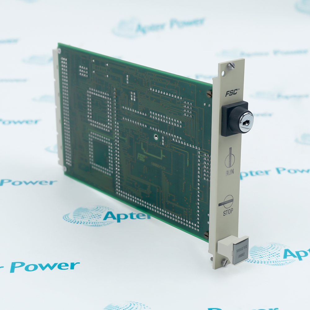
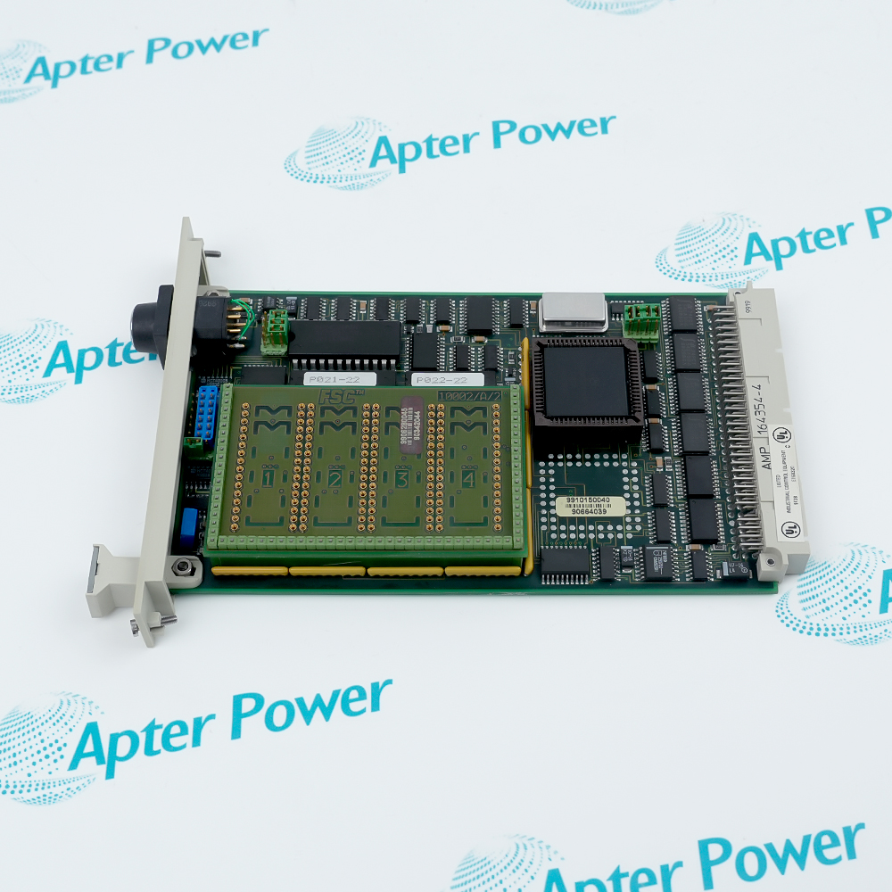
Features:
- FSC central processor executes system and application programs
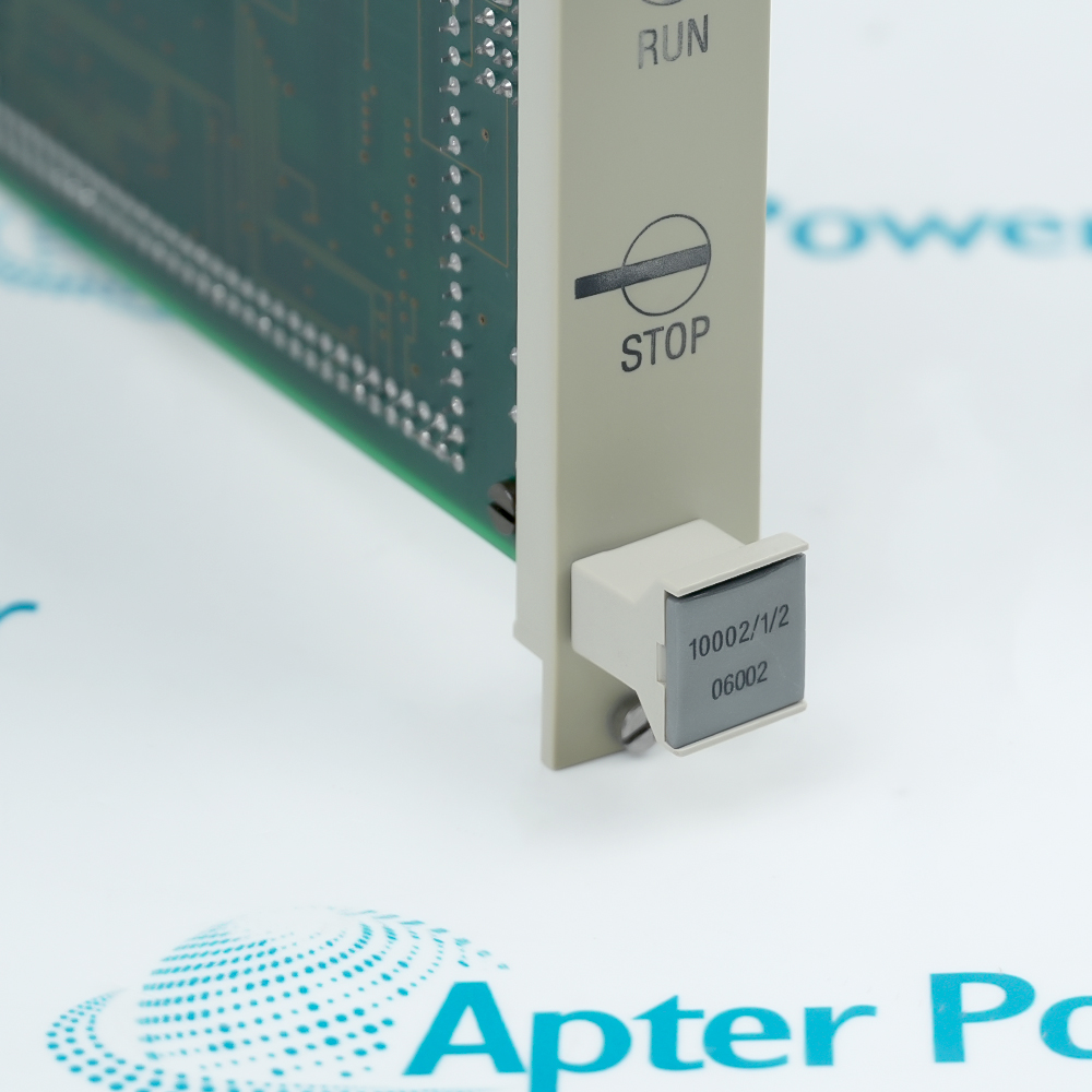
- Front key switch selects RUN or STOP with hardware CPU reset
- Separate 10002/A/1 module carries system EPROM and application memory
The CPU divides volatile memory between system variables and the application program, so controller operation and user logic use distinct RAM areas.
Battery backup reaches the processor RAM from Central Part support hardware, linking data retention to the diagnostic/battery or single-bus-driver path.
The processor and its 10002/A/1 board share the specified 5 V DC load and occupy one four-HP, three-U assembly position.
The Honeywell 10002/1/2 FSC Central Processor Unit Module may still be available for purchase and support from Apter Power beyond End-Of-Life (EOL) by the manufacturer (OEM).
Honeywell 10002/1/2 FSC Central Processor Unit Module Manuals,Datasheets,Link
Important Notice: Other accessories, manuals, cables, calibration data, software, etc. are not included with this equipment unless listed in the above stock item description. All prices are shown in USD.
RUN and STOP hardware behavior
- RUN position: The vertical key position permits the processor to run.
- STOP position: The horizontal position stops the CPU and applies a hardware reset.
- Reset action: The key function acts on the processor rather than only changing an operator indication.
How CPU and memory board divide storage
- System RAM: System RAM holds variables, I/O data, markers, counters, timers, and registers.
- Application RAM: Application RAM on the CPU can execute smaller programs without extra memory devices.
- Board division: The 10002/A/1 board carries system EPROM and larger application EPROM or RAM devices.
Retaining RAM when external power is lost
- Backup source: CPU RAM is connected to a battery-backed supply path.
- Data retention: The diagnostic and battery module or single bus driver provides that backup source.
- Power loss: The retention circuit is external to the CPU faceplate and depends on Central Part support hardware.
Shared load and live-removal restriction
- Logic supply: The stated 5 V DC load includes both CPU and 10002/A/1 memory module.
- Current load: Ripple on the logic supply remains below the documented peak-to-peak limit.
- Removal limit: The module is removed only after Central Part power has been isolated.