Ask our team:
  • Phone: +86 181 0690 9650
  • E-Mail info@apterpower.com

RH101RY

/ 4.9
1001 reviews | Need a Specific Revision?
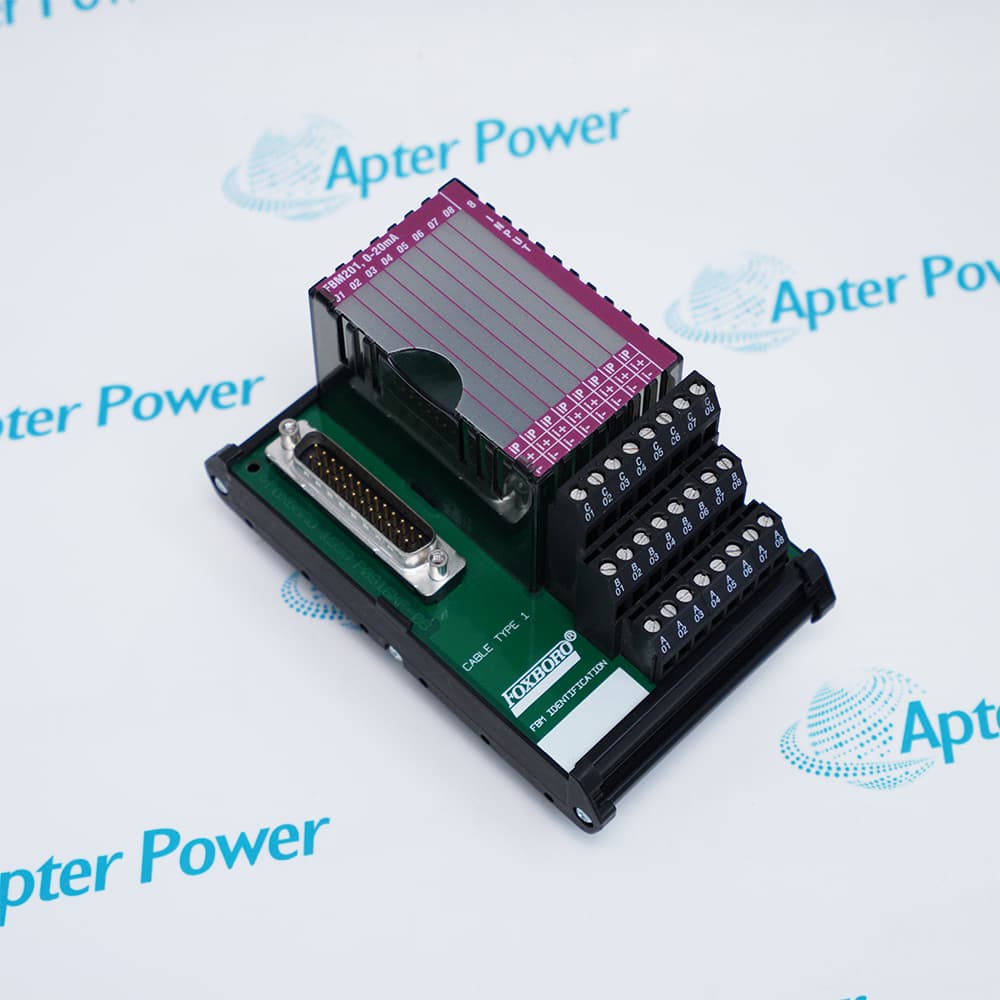
Foxboro RH101RY is the group-isolated internal-power termination assembly for sixteen Compact FBM214E 4–20 mA/HART input loops.
In Stock
Ships by Saturday, October 17
Fast Shipping Available
Get a quick price for RH101RY
Quantity
*E-mail
Company
*Mobile
*Content
Upload (gif, jpg, jpeg, png, bmp, doc, docx, xls, xlsx, ppt, pdf, csv)

Technical specifications for RH101RY

  • Manufacturer:
    Invensys
  • Part Number:
    RH101RY
  • Product Family:
    Foxboro
  • Product Type:
    Internal-Power Termination Assembly for Compact FBM214E
  • Stock:
    1
  • Compatible module:
    Compact FBM214E / RH101RP
  • Input channels:
    16
  • Signal:
    4 to 20 mA with or without HART
  • Loop power source:
    FBM auxiliary +24 VDC supply
  • Input resistance:
    298 Ω including TA
  • Termination:
    Compression terminals
  • Mounting:
    32 mm or 35 mm DIN rail
  • Cable type:
    Type 4
  • Weight:
    0.272 kg
  • Tariff Code:
    8536909000
  • Country of origin:
    USA
  • Place of shipment:
    Xiamen, Fujian, China
By purchasing this item, you agree to the Terms & Conditions, ApterPower is not an authorized distributor for listed manufacturers or tradenames and therefore the manufacturer's warranty does not apply. All our products come with ApterPower's 1-year warranty.

More Information

Overview Manuals Loop Power Field Wiring Replacement Checks Application
  • Confirm RH101RY is required instead of the externally powered RH101RT
  • Use RH101RY only with the documented Compact FBM214E module and Type 4 cable
  • Check the shared internal loop-power budget before connecting transmitters

Foxboro RH101RY is the exact internal-power termination assembly for Compact FBM214E input channels.

It provides sixteen compression-terminal field connections and supplies loop power from the FBM auxiliary 24 VDC source.

Before installation, verify the TA label, compatible module, cable part number, DIN-rail space, channel terminal map and transmitter load.

Availability, condition, price, and shipping time for RH101RY are confirmed during quotation.

Foxboro RH101RY Manuals, Datasheets, Links

Important Notice: Other accessories, manuals, cables, calibration data, software, etc. are not included with this equipment unless listed in the above stock item description. All prices are shown in USD.

  • The TA uses the FBM auxiliary +24 VDC supply
  • One supported field device is powered per channel
  • All loop supplies are current-limited by the documented design
  • Sixteen compression-terminal input circuits are provided
  • A Type 4 cable links the TA to the Compact baseplate
  • Shielding and polarity must follow the installed loop drawings
  • Confirm RH101RY rather than the external-power RH101RT
  • Preserve terminal numbering and loop assignments
  • Prove current and HART communication channel by channel
  • Internally powered 4–20 mA/HART transmitter termination
  • Compact FBM214E field-loop connection
  • DIN-rail termination for group-isolated analog input loops
Description
Foxboro RH101RY terminates sixteen 4–20 mA signals, with or without HART data, for a Compact FBM214E module.

Its internal-power arrangement feeds one supported field device per channel and provides group isolation and current limiting as part of the documented module/TA combination.

The assembly is used when a Compact FBM214E station is designed to power its transmitter loops without a separate customer loop supply.
Alternative Names
RH 101 RY Foxboro RH101RY Foxboro RH 101 RY Invensys Foxboro RH101RY Invensys Foxboro RH 101 RY FBM214e RH101RY Compact FBM214e RH101RY Foxboro FBM214e RH101RY
Technical notes
RH101RY is a termination assembly, not the FBM214E electronics module. Its official approximate mass is 0.272 kg; a reliable three-axis body dimension is not stated in extractable official text and is left blank.
Exceptional Service

Our Mission

  • 100% Satisfaction

    We believe expertise is priceless. With over 20 years of experience, and top engineers on staff, we can help you solve or avoid problems that threaten your business.
  • Trust Guaranteed

    Not only do we have a vast inventory, our team makes sure every piece of equipment is in working condition. Your purchases are also backed by our Warranty.
  • Expertise

    Time is money, especially when your equipment is down. We work quickly to get your equipment on its way so you can get it back up and running.

FAQS

The following is a list of questions commonly asked by our customers. Please contact us if you have a question about our process that is not answered below.
Can Foxboro RH101RY replace RH101RT without changing loop wiring?
Not automatically. RH101RY uses FBM auxiliary loop power, while RH101RT is for customer-supplied external loop power; the power and grounding design must be reviewed.
Can Foxboro RH101RY replace an externally powered FBM214e termination assembly without wiring changes?
No. Foxboro RH101RY uses the FBM auxiliary 24 VDC supply for field-loop power, so confirm the termination assembly, terminal assignments and loop-power wiring before replacement.
Why might a field transmitter remain unpowered after installing Foxboro RH101RY?
Verify that Foxboro RH101RY receives the required auxiliary 24 VDC supply, then check loop polarity, common connections, terminal assignments and the connected FBM214e channel wiring.
Can Foxboro RH101RY power two transmitters from one channel?
No. The documented internal-power arrangement is limited to one field device per channel.
Why can all Foxboro RH101RY loops lose power while the module still communicates?
Check the auxiliary 24 VDC source, TA cable, group power path and current limiting; module fieldbus communication does not prove loop power is present.
What must be documented before replacing Foxboro RH101RY?
Record the terminal-to-channel map, loop polarity, transmitter load, shield and ground arrangement, Type 4 cable, DIN-rail position and compatible module slot.
How should Foxboro RH101RY be tested after installation?
Verify loop voltage and current on every channel, confirm HART communication where used, test open-loop diagnostics and prove the mapped process values before returning control to service.

Product Browsing History