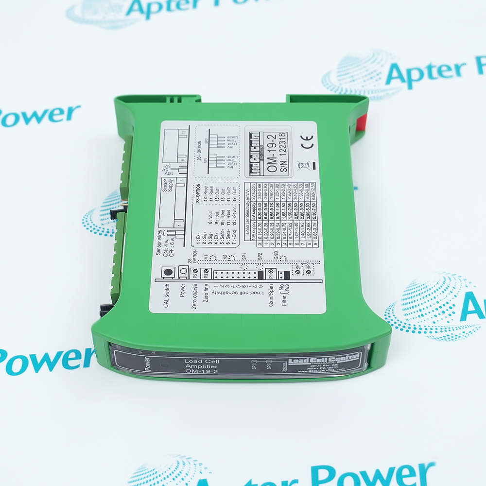
Features:
- DIN-rail housing integrates load-cell conditioning inside a control cabinet.
- One module can excite up to four 350 Ω strain-gauge load cells.
- Selectable voltage or current output matches common controller analog inputs.
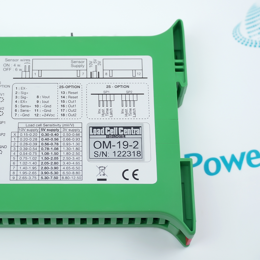
Four- and six-wire sensor selections let the terminal arrangement follow the actual load-cell cable and available sense conductors.
Zero and span controls work with the chosen excitation and analog-output mode, so calibration should be completed after wiring selections are fixed.
A shunt-calibration input and measurement points support verification without changing the mechanical load during every electrical check.
The Load Cell Central OM-19-2 DIN-Rail Analog Load Cell Signal Conditioner may still be available for purchase and support from Apter Power beyond End-Of-Life (EOL) by the manufacturer (OEM).
Load Cell Central OM-19-2 DIN-Rail Analog Load Cell Signal Conditioner Manuals,Datasheets,Link
Important Notice: Other accessories, manuals, cables, calibration data, software, etc. are not included with this equipment unless listed in the above stock item description. All prices are shown in USD.
Preparing the strain-gauge connection
- Cell count: The conditioner can energize up to four 350 Ω load cells.
- Cable selection: Set the input for a four- or six-wire sensor before calibration.
- Excitation: Choose 3, 5, or 10 V to suit the connected bridge network.
- Sense conductors: On six-wire installations, confirm the sense pair reaches the load-cell terminals rather than stopping at the cabinet.
Matching the receiving analog input
- Bipolar voltage: Select ±10 V when the controller must receive positive and negative measurement direction.
- Unipolar voltage: Use 0–10 V only with an input impedance of at least 2000 Ω.
- Current loop: The 4–20 mA path supports a loop load up to 500 Ω.
- Output loading: Keep connected capacitance within the documented 1 nF limit.
Establishing zero, span, and response
- Zero setting: Remove mechanical load and stabilize excitation before trimming the zero point.
- Span range: Set gain within the documented 0.15 to 12 mV/V sensor range.
- Shunt check: Use the calibration control to verify a repeatable electrical response without altering the load.
- Filtering: Engage the 10 Hz low-pass option only when its response time still fits the weighing process.
Cabinet and supply checks
- Rail position: Allow space for the 130 x 111 x 22.5 mm DIN-rail housing and terminal wiring.
- DC source: Maintain the supply inside 24 ±4 V DC under load.
- Thermal limit: Keep operating temperature between 0 and +70 °C.
- Commissioning order: Confirm wiring and jumpers before applying known-load points for final scaling.