Features:
- Compares the incoming counter value with independently set lower and upper limits.
- Shows -NG, OK, and +NG results through dedicated colored indicators.
- Transfers the judgment to external control wiring through relay contacts.
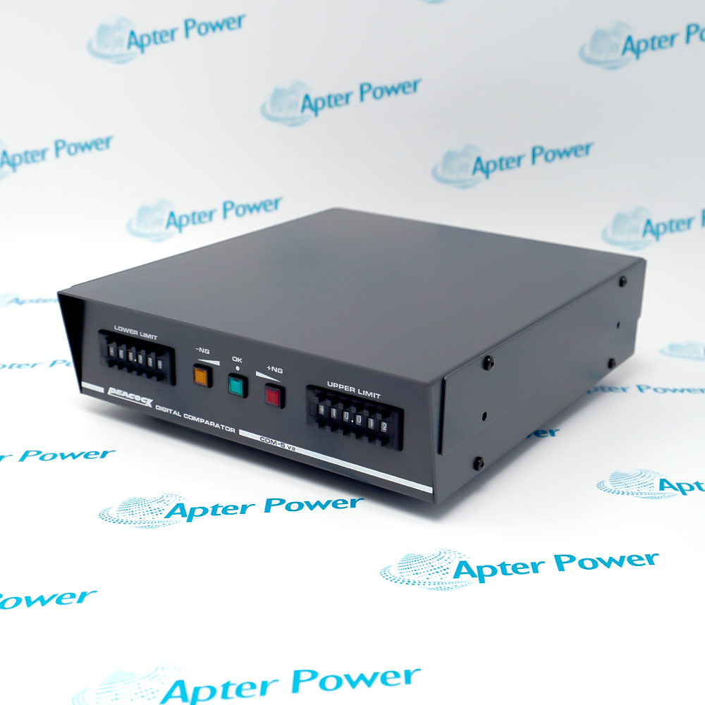
PEACOCK COM-5 V2 extends a compatible C-5 or C-5S counter with a separate pass/fail judgment stage.
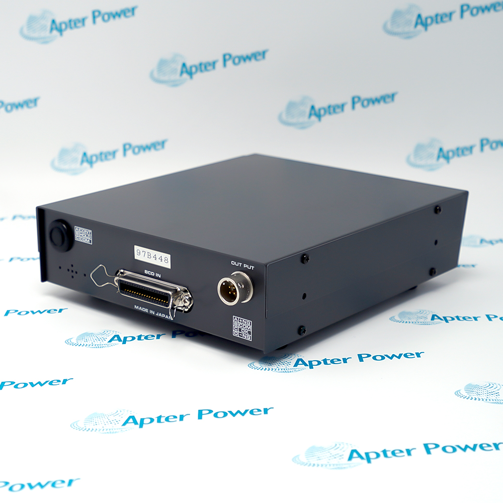
The BCD input carries the measurement value into the comparator while the front switches establish the decision boundaries.
Visual indicators and relay contacts report the same three-state result to the operator and the connected control circuit.
The PEACOCK COM-5 V2 Digital Limit Comparator may still be available for purchase and support from Apter Power beyond End-Of-Life (EOL) by the manufacturer (OEM).
PEACOCK COM-5 V2 Digital Limit Comparator Manuals,Datasheets,Link
Important Notice: Other accessories, manuals, cables, calibration data, software, etc. are not included with this equipment unless listed in the above stock item description. All prices are shown in USD.
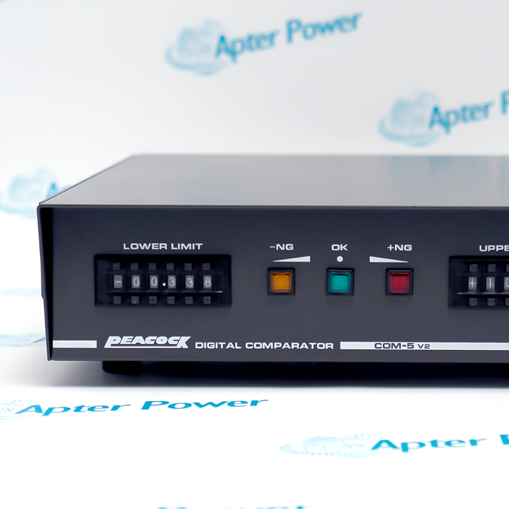
Lower and upper decision boundaries
- Lower switch: The signed five-digit LOWER bank establishes the negative-side judgment boundary.
- Upper switch: The signed five-digit UPPER bank establishes the positive-side judgment boundary.
- Documented span: The COM-5 setting range extends from -99.999 to +99.999.
- Boundary behavior: The documented factory arrangement treats the lower set value as OK and the upper set value as NG.
Three-result indication path
- Below range: The yellow -NG lamp identifies a value below the accepted band.
- Accepted range: The blue OK lamp identifies a value within the configured band.
- Above range: The red +NG lamp identifies a value above the accepted band.
- Continuous comparison: One of the three states remains indicated while judgment is enabled.
Discrete result transfer
- Contact form: The comparator uses protected normally open relay contacts.
- AC boundary: The documented AC contact capacity is 110 V at 5 VA.
- DC boundary: The documented DC contact capacity is 30 V at 1 A.
- Response: The relay-dependent judgment response is approximately 20 ms or less.
Value, power, and control connections
- Measurement path: BCD IN receives the displayed value from the compatible counter.
- Power path: The connected counter supplies 12 V DC at 80 mA to the comparator.
- Output path: The OUTPUT connector carries the three-state relay judgment.
- Control terminals: CONT, HOLD, and COM provide the documented external control references.