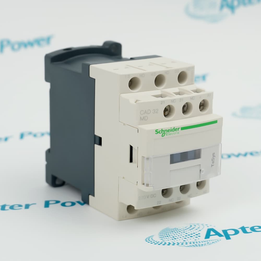
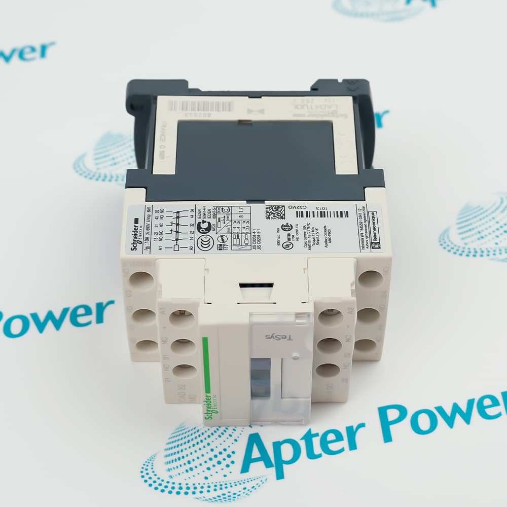
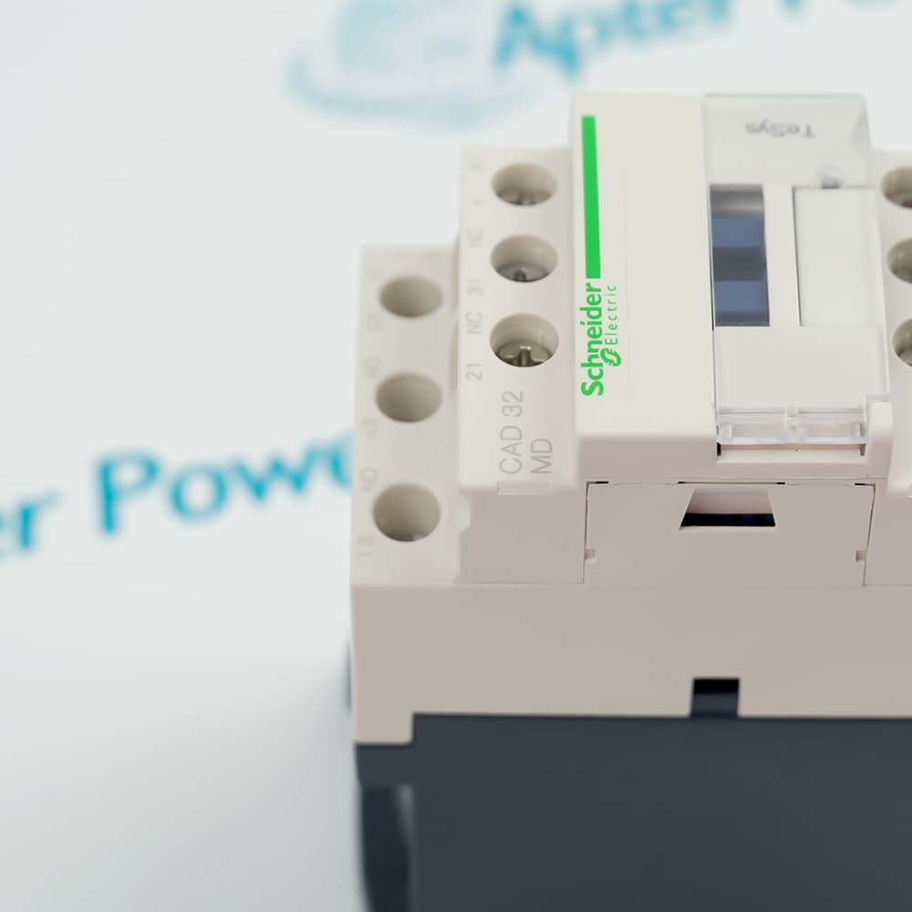
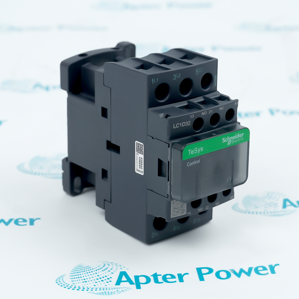
Features:
- Five auxiliary contacts arranged as 3 NO + 2 NC
- Standard 220 V DC control coil
- Rail or plate installation with screw-clamp terminals
CAD32MD is the TeSys CAD configuration intended for auxiliary control-circuit duties where three make contacts and two break contacts are required in one relay.
Its documented utilisation categories cover electromagnetic-load and control-device switching, allowing the relay to coordinate interlocks, status logic, and control sequences within the approved ratings.
Before procurement, compare the exact coil voltage, pole logic, conductor size, terminal accessories, mounting arrangement, protective device, and ambient conditions with the electrical design.
Availability is subject to Apter Power's current inventory and sourcing confirmation.
Schneider Electric CAD32MD TeSys Deca Control Relay, 3 NO + 2 NC, 220 V DC Coil Manuals, Datasheets, Link
Important Notice: Other accessories, manuals, cables, calibration data, software, etc. are not included with this equipment unless listed in the above stock item description. All prices are shown in USD.
Schneider Electric CAD32MD TeSys Deca Control Relay, 3 NO + 2 NC, 220 V DC Coil Specs
General
- ManufacturerSchneider Electric
- ModelCAD32MD
- ConditionNew Original ready stock
- Product FamilySchneider Electric TeSys Deca Control Relays
Important Notice: Other accessories, manuals, cables, calibration data, software, etc. are not included with this equipment unless listed in the above stock item description. All prices are shown in USD.
Control-circuit application review
- Relay logic: Map each normally open and normally closed contact to the approved sequence before wiring.
- Interlocking: Confirm that the electrical interlock logic reaches a defined state during coil loss.
- Load category: Check the connected control load against AC-14, AC-15, or DC-13 requirements.
- Switching rate: Keep the operating sequence within the documented mechanical and thermal limits.
Mounting and termination checks
- Mounting: Use the approved rail or plate arrangement and keep the relay securely seated.
- Conductors: Select conductor size and preparation that match the screw-clamp terminal instructions.
- Torque: Tighten terminals to the documented 1.7 N·m value with the specified screwdriver type.
- Coil circuit: Verify the 220 V DC supply and control wiring before energizing the relay.
Documented operating boundaries
- Protection: The front face is rated IP2X when installed as specified.
- Temperature: Apply the manufacturer derating instructions above 60 °C.
- Standards: Retain evidence for IEC, UL, CSA, and other required approvals in the machine file.
- Isolation: Follow the machine isolation procedure before changing coil or contact wiring.