XS4P18AB120
XS4P18AB120
XS4P18AB120
XS4P18AB120
XS4P18AB120
XS4P18AB120
Ask our team:
  • Phone: +86 181 0690 9650
  • E-Mail sales1@apterpower.com
  • Lifecycle status

    Active / Available from OEM
    Apter supplies XS4P18AB120 with catalog and application verification.

XS4P18AB120

/ 4.9
1001 reviews | Need a Specific Revision?
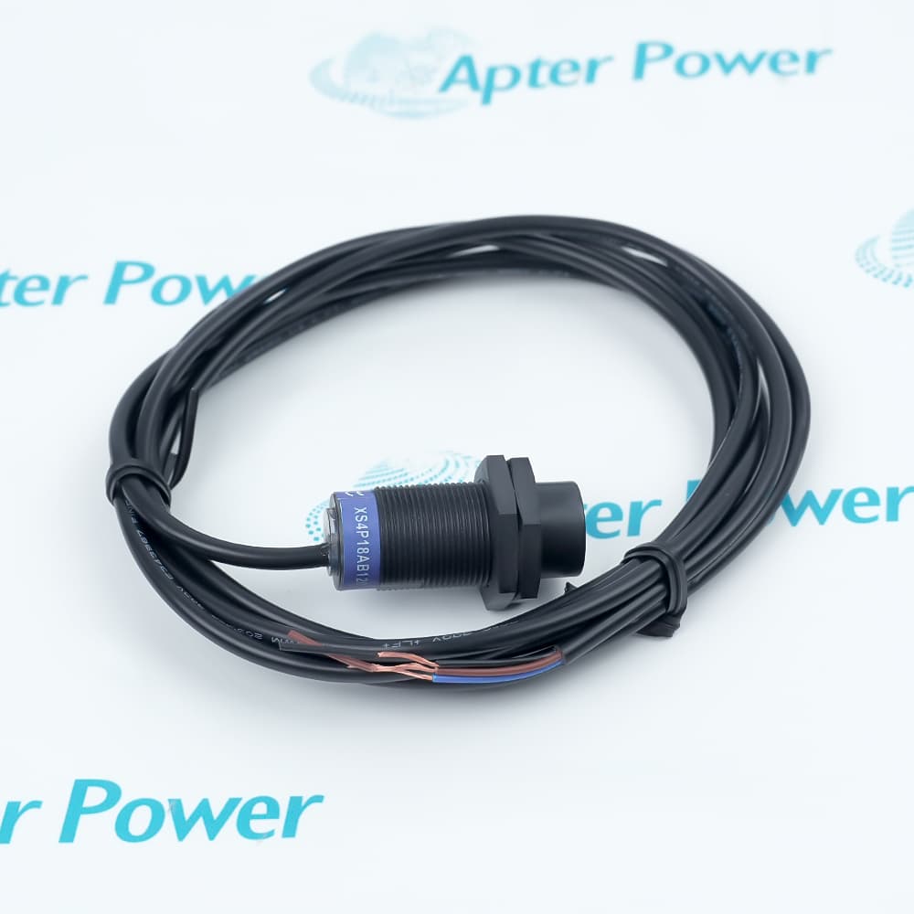
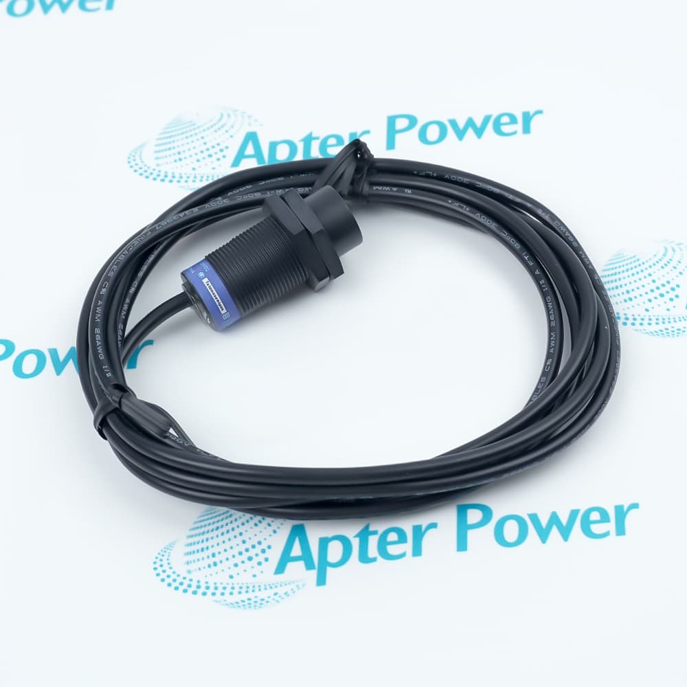
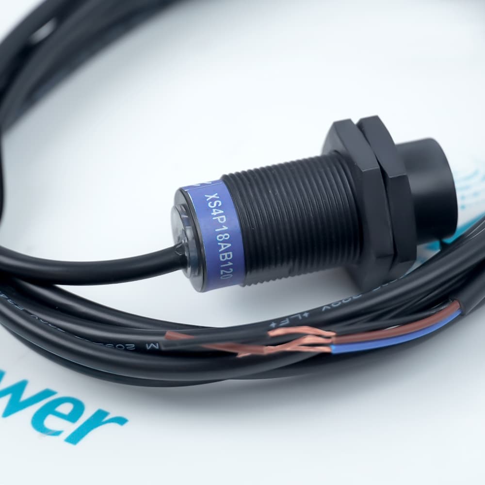
Telemecanique XS4 M18 non-flush inductive sensor with 8 mm range and 4-20 mA analog output.
In Stock
Ships by Thursday, October 29
Fast Shipping Available
Get a quick price for XS4P18AB120
Quantity
*E-mail
Company
*Mobile
*Content
Upload (gif, jpg, jpeg, png, bmp, doc, docx, xls, xlsx, ppt, pdf, csv)

Technical specifications for XS4P18AB120

  • Manufacturer:
    Schneider Electric
  • Part Number:
    XS4P18AB120
  • Product Family:
    Telemecanique Sensors
  • Product Type:
    M18 Inductive Analog Sensor
  • Stock:
    1
  • Body:
    M18 cylindrical, non-flush
  • Nominal sensing distance:
    8 mm
  • Analog output:
    4-20 mA, two-wire
  • Supply:
    12-24 V DC
  • Cable:
    2 m
  • Protection:
    IP67
  • Operating temperature:
    -25 to 70 degrees C
  • Weight:
    0.08 kg
  • Estimated shipping dimensions:
    1.8x1.8x4.1cm
  • Tariff Code:
    8536500000
  • Country of origin:
    France
  • Place of shipment:
    Xiamen,Fujian,China
By purchasing this item, you agree to the Terms & Conditions, ApterPower is not an authorized distributor for listed manufacturers or tradenames and therefore the manufacturer's warranty does not apply. All our products come with ApterPower's 1-year warranty.

More Information

Overview Manuals Analog Output Sensing Distance Mounting Boundary Product Applications

Features:

  • Analog target feedback: The sensor reports changing metal-target position through a continuous current signal.
  • Non-flush M18 form: Its cylindrical body is designed for a mounting arrangement that leaves the sensing face clear of surrounding metal.
  • Integrated connection: The attached cable provides a ready two-wire path to the receiving analog input.
XS4P18AB120 is useful where a control system needs more information than a simple target-present or target-absent signal. Its analog response lets the receiving system observe movement within the sensor's usable range.

The device turns a compact inductive sensing point into a continuous feedback channel for metal targets. This makes mechanical position, target approach, or clearance available to control and monitoring logic.

Its selection depends on the relationship between the target, the mounting geometry, and the analog input. The non-flush body and integrated cable make physical installation part of the sensing decision, not a separate afterthought.

Apter Power can help review official product documentation and coordinate a quotation for XS4P18AB120 sourcing.
Schneider Electric XS4P18AB120 M18 Inductive Analog Sensor Manuals,Datasheets,Link Important Notice: Other accessories, manuals, cables, calibration data, software, etc. are not included with this equipment unless listed in the above stock item description. All prices are shown in USD.
  • Two-wire output provides a 4-20 mA analog signal
  • Scale the receiving input to the measured target position
  • Verify loop voltage and input burden before commissioning
  • Nominal sensing distance is 8 mm
  • Target material and geometry affect the usable range
  • Validate endpoints on the actual machine target
  • Install as a non-flush sensor
  • Maintain the required surrounding metal clearance
  • Protect the attached 2 m cable from strain and abrasion
  • Continuous metal-target position monitoring
  • Analog approach-distance feedback on machinery
  • Replacement in documented 4-20 mA inductive sensing loops
Description
XS4P18AB120 is a cylindrical M18 inductive analog sensor in the Telemecanique XS4 range. The official datasheet identifies non-flush mounting, an 8 mm nominal sensing distance, a two-wire 4-20 mA output, 12-24 V DC supply, and an attached 2 m cable.

XS4P18AB120 is intended for continuous metal-target position or distance indication within its stated sensing envelope. Selection should verify target material, non-flush clearance, analog-loop scaling, cable routing, IP67 enclosure conditions, and the -25 to 70 degrees Celsius operating range.
Alternative Names
XS4 P18 AB120 M18 4-20 mA Inductive Sensor
Technical notes
XS4P18AB120 is a non-flush M18 analog inductive sensor, not a discrete proximity switch. Verify the two-wire 4-20 mA loop, 12-24 V DC supply, target material, mounting clearance, cable condition, and input scaling before replacement. Commission the measured position at the actual target geometry and operating temperature.
Exceptional Service

Our Mission

  • 100% Satisfaction

    We believe expertise is priceless. With over 20 years of experience, and top engineers on staff, we can help you solve or avoid problems that threaten your business.
  • Trust Guaranteed

    Not only do we have a vast inventory, our team makes sure every piece of equipment is in working condition. Your purchases are also backed by our Warranty.
  • Expertise

    Time is money, especially when your equipment is down. We work quickly to get your equipment on its way so you can get it back up and running.

FAQS

The following is a list of questions commonly asked by our customers. Please contact us if you have a question about our process that is not answered below.
Can XS4P18AB120 be mounted flush with surrounding metal?
No. It is a non-flush M18 analog sensor, so surrounding metal clearance must follow the installation requirement; a flush pocket can change the usable sensing response.
Why does XS4P18AB120 need an analog input rather than a discrete proximity input?
Its two-wire output is 4-20 mA and represents target approach as an analog value. Use a compatible current input and scale it to the machine's measured endpoints.
When can the 8 mm nominal range of XS4P18AB120 not be used as the trip point?
Do not treat 8 mm as a guaranteed machine threshold when target material, size, alignment, or mounting metal differs from the reference conditions. Validate the endpoints on the real target.
How should loop burden be checked before commissioning XS4P18AB120?
Confirm the 12-24 V DC loop supply can drive the receiving input and cable resistance across the required current range. Stop if the available voltage margin is insufficient.
Which mechanical detail must match when replacing XS4P18AB120?
Match the non-flush M18 body, target geometry, and attached 2 m cable route. A sensor with the same signal but different mounting behavior is not a like-for-like mechanical replacement.
Before accepting XS4P18AB120, how should the 4-20 mA endpoints be proven?
Move the actual target through the required machine range and compare the measured current with the configured input scaling. Correct mounting or scaling before enabling automatic control.