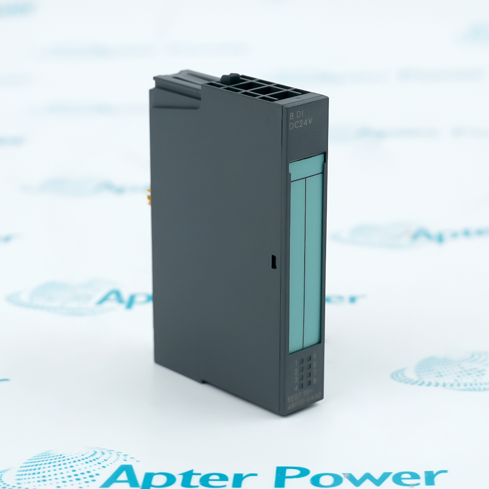
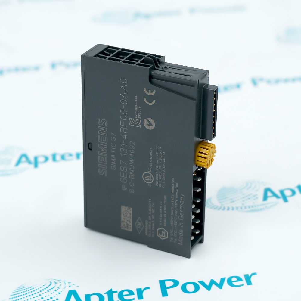
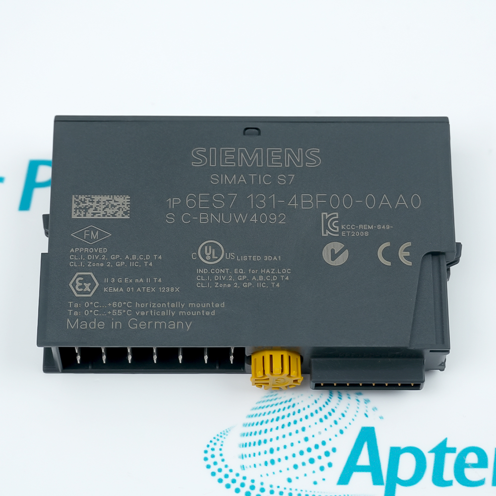
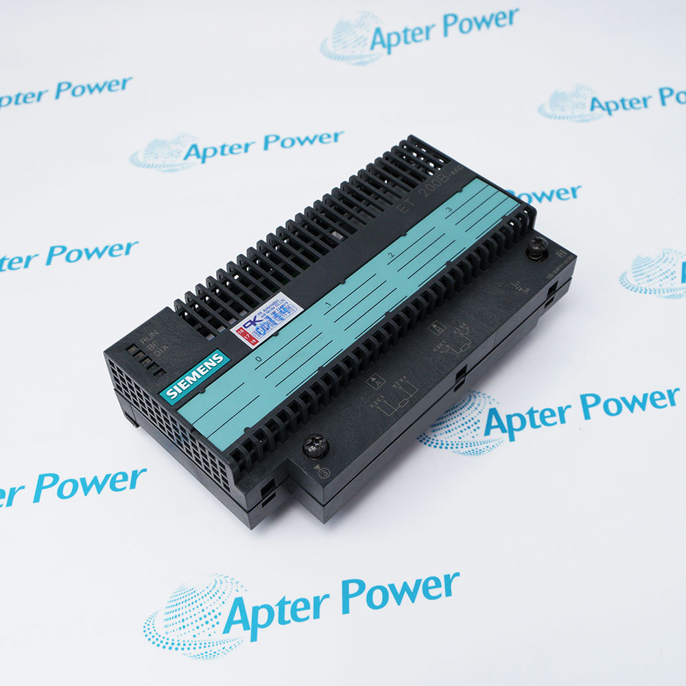
Features:
- Eight Type 1 inputs acquire 24 V DC states from connected two-wire sensors.
- The module maps all eight channel states into one input byte on the ET 200S backplane.
- Green LEDs indicate channel state while galvanic separation isolates the input group from the backplane.
Siemens 6ES7131-4BF00-0AA0 turns eight field voltage states into the digital byte read by the station interface.
The input channels of 6ES7131-4BF00-0AA0 share their field-side potential but remain isolated as a group from the backplane bus.
Isochronous operation aligns the acquisition timing of 6ES7131-4BF00-0AA0 with the configured automation cycle.
The Siemens 6ES7131-4BF00-0AA0 ET 200S 8-Channel 24 V DC Digital Input Module may still be available for purchase and support from Apter Power beyond End-Of-Life (EOL) by the manufacturer (OEM).
Siemens 6ES7131-4BF00-0AA0 ET 200S 8-Channel 24 V DC Digital Input Module Manuals,Datasheets,Link
Important Notice: Other accessories, manuals, cables, calibration data, software, etc. are not included with this equipment unless listed in the above stock item description. All prices are shown in USD.
Eight 24 V DC Sensor Channels
- Signal 0: Input voltages from -30 to +5 V are interpreted as the low state.
- Signal 1: Input voltages from +15 to +30 V are interpreted as the high state.
- Input current: A high-state channel draws approximately 5 mA.
- Input delay: Both signal transitions use the documented 2 to 4.5 ms delay range.
Field Potential and Cable Reach
- Sensor type: Two-wire sensors can be connected within the stated quiescent-current limit.
- Shared potential: The eight input channels are not galvanically separated from one another.
- Shielded cable: A shielded input circuit may extend to 1,000 m.
- Unshielded cable: An unshielded input circuit is limited to 600 m.
Address and Isolation Path
- Input image: All eight channel states occupy one byte in the controller input area.
- Electronics supply: The module draws up to 10 mA from the 3.3 V DC backplane bus.
- Group isolation: The complete input group is galvanically separated from the backplane.
- Proof test: The isolation path is tested at 500 V DC.
Synchronized Acquisition and Indication
- Isochronous mode: The terminal-to-backplane acquisition path supports synchronized operation.
- TWE value: The documented input time for isochronous operation is 3,000 µs.
- Channel LEDs: One green LED reports the signal state of each digital input.
- Diagnostic limit: The module does not send diagnostic messages for channel faults.