Ask our team:
  • Phone: +86 181 0690 9650
  • E-Mail sales1@apterpower.com
  • Lifecycle status

    Discontinued / Obsolete by OEM
    Apter Power provides 6ES7131-1BL11-0XB0 quotations, manuals, wiring review, and exact-block matching.

6ES7131-1BL11-0XB0

/ 4.9
1001 reviews | Need a Specific Revision?
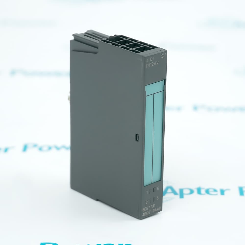
The Siemens 6ES7131-1BL11-0XB0 ET 200L-SC digital input electronic block collects thirty-two 24 V DC field signals and transfers their states over PROFIBUS-DP.
In Stock
Ships by Wednesday, October 28
Fast Shipping Available
Get a quick price for 6ES7131-1BL11-0XB0
Quantity
*E-mail
Company
*Mobile
*Content
Upload (gif, jpg, jpeg, png, bmp, doc, docx, xls, xlsx, ppt, pdf, csv)

Technical specifications for 6ES7131-1BL11-0XB0

  • Manufacturer:
    Siemens
  • Part Number:
    6ES7131-1BL11-0XB0
  • Product Family:
    Siemens Simatic DP
  • Product Type:
    ET 200L-SC 32-Channel Digital Input Electronic Block
  • Stock:
    1
  • Digital Inputs:
    32
  • Input Grouping:
    2 groups of 16
  • Rated Input Voltage:
    24 V DC
  • Signal 1 Range:
    13 to 30 V
  • Signal 0 Range:
    -30 to +5 V
  • Signal 1 Current:
    Typically 5 mA at 24 V
  • Input Delay:
    2.0 to 4.5 ms
  • Input Characteristic:
    IEC 1131-2 Type 1
  • Two-Wire Proximity Sensors:
    Permitted
  • Permissible Sensor Leakage Current:
    Maximum 1.5 mA
  • Bus Protocol:
    PROFIBUS-DP
  • PROFIBUS Rates:
    9.6 to 1500 kbit/s
  • Unshielded Bus Cable:
    Maximum 600 m
  • Shielded Bus Cable:
    Maximum 1000 m
  • Channel-to-Bus Isolation:
    Yes
  • Isolation Test Voltage:
    500 V DC
  • Power Failure Withstand:
    At least 20 ms
  • Typical Power Loss:
    4.8 W
  • Status Indication:
    Green LED per channel; ON, BF and group-error LEDs
  • Terminal Block Interface:
    TB 16SC Smart Connect
  • Weight:
    0.3307 lbs (0.15 kg)
  • Estimated shipping dimensions:
    14.5x6x6.05cm
  • Tariff Code:
    85389091
  • Country of origin:
    Germany
  • Place of shipment:
    Xiamen,Fujian,China
By purchasing this item, you agree to the Terms & Conditions, ApterPower is not an authorized distributor for listed manufacturers or tradenames and therefore the manufacturer's warranty does not apply. All our products come with ApterPower's 1-year warranty.

More Information

Overview Manuals Input Groups Smart Connect PROFIBUS Path Fault Indicators

Features:

  • Thirty-two 24 V DC inputs are organized as two groups of sixteen.
  • The TB 16SC connection adds the Smart Connect extension path.
  • PROFIBUS-DP transfers input states and module diagnostic information.
Field voltage crosses a channel threshold before the corresponding process bit is updated.

Load groups keep their supply and common paths tied to the documented terminal organization.

ON, BF, group-error, and individual channel LEDs identify different parts of the signal path.

The Siemens 6ES7131-1BL11-0XB0 ET 200L-SC Digital Input Electronic Block may remain available for quotation and support beyond End-Of-Life (EOL) by the manufacturer (OEM).
Siemens 6ES7131-1BL11-0XB0 ET 200L-SC Digital Input Electronic Block Manuals,Datasheets,Link Important Notice: Other accessories, manuals, cables, calibration data, software, etc. are not included with this equipment unless listed in the above stock item description. All prices are shown in USD.

Relating terminal groups to the process image

  • Channels 1 to 16: The first group shares its assigned load and common terminals.
  • Channels 17 to 32: The second group follows its separate documented group path.
  • Signal thresholds: Input voltage determines whether the PLC reads a zero or one.
  • Channel LEDs: Each green indicator follows the state of its individual input.

Extending the station from the TB 16SC interface

  • Cable set: The short Smart Connect lead links the electronics block to the extension terminal block.
  • Added modules: Configured digital or analog modules occupy the Smart Connect address area.
  • Open interface: The SC cover closes an unused interface before operation.
  • Project match: The hardware order and PROFIBUS configuration describe the same extension layout.

Moving field states from the input electronics to the controller

  • Bus address: The station address identifies the block on PROFIBUS-DP.
  • Transfer rate: The selected rate follows the segment configuration.
  • Isolation: The channel section is galvanically separated from the bus interface.
  • Cable length: Shielding and baud rate are checked against the documented segment limits.

Separating signal state from supply and bus conditions

  • Channel status: Green LEDs report the individual input states.
  • ON indicator: The electronics-supply LED shows the internal power condition.
  • BF indicator: The red bus-fault LED identifies disrupted PROFIBUS communication.
  • Group error: The red group indication signals a module-level diagnostic condition.
Description
In the ET 200L-SC distributed I/O system, Siemens 6ES7131-1BL11-0XB0 is the 32-channel digital input electronics block that samples 24 V DC switches and proximity sensors and places their states on PROFIBUS-DP. Its on-board inputs form the base digital acquisition section before any Smart Connect modules are added.

The inputs of 6ES7131-1BL11-0XB0 are divided into two groups of sixteen, with assigned load-voltage and common paths for each group. A field signal must cross the documented voltage threshold at the correct terminal before the associated channel LED and process bit change state.

Through the TB 16SC connection, 6ES7131-1BL11-0XB0 accepts the Smart Connect cable set used for additional digital or analog modules. The PROFIBUS process image then combines the on-board 32 inputs with the configured Smart Connect address area rather than treating the extension as an unrelated station.

Diagnostics on 6ES7131-1BL11-0XB0 separate channel status from electronics supply, group error, and bus-fault conditions. Galvanic isolation lies between the channel section and PROFIBUS-DP, while channels inside the input section share their group-related electrical references.
Alternative Names
6ES71311BL110XB0 6ES7 131-1BL11-0XB0 6ES7131 1BL11 0XB0 Siemens 6ES7131-1BL11-0XB0 6ES7131-1BL11-0XB0 L-SC 32 DI ET 200L-SC 6ES7131-1BL11-0XB0 6ES 7131 1BL11 0XB0 6ES7131/1BL11/0XB0
Technical notes
For Siemens 6ES7131-1BL11-0XB0, verify both 16-channel load groups, TB 16SC wiring, PROFIBUS address, sensor leakage current, and Smart Connect configuration.
Exceptional Service

Our Mission

  • 100% Satisfaction

    We believe expertise is priceless. With over 20 years of experience, and top engineers on staff, we can help you solve or avoid problems that threaten your business.
  • Trust Guaranteed

    Not only do we have a vast inventory, our team makes sure every piece of equipment is in working condition. Your purchases are also backed by our Warranty.
  • Expertise

    Time is money, especially when your equipment is down. We work quickly to get your equipment on its way so you can get it back up and running.

FAQS

The following is a list of questions commonly asked by our customers. Please contact us if you have a question about our process that is not answered below.
Why does one input group on Siemens 6ES7131-1BL11-0XB0 remain inactive?
Measure the Siemens 6ES7131-1BL11-0XB0 load voltage and common for that 16-channel group, then compare terminal state, channel LED, and process bit.
How should Smart Connect be checked on 6ES7131-1BL11-0XB0?
For 6ES7131-1BL11-0XB0, verify the TB 16SC cable set, connector orientation, installed extension modules, closed unused interface, and matching PROFIBUS configuration.
What does the BF LED indicate on Siemens 6ES7131-1BL11-0XB0?
The Siemens 6ES7131-1BL11-0XB0 BF indication points to PROFIBUS communication; inspect address, rate, cable, connectors, termination, and master configuration.
Can a two-wire proximity sensor connect directly to 6ES7131-1BL11-0XB0?
Yes, if the 6ES7131-1BL11-0XB0 input voltage and the sensor closed-circuit current remain within the documented limits.
Which data should be recorded before replacing Siemens 6ES7131-1BL11-0XB0?
Record the Siemens 6ES7131-1BL11-0XB0 PROFIBUS address, baud rate, terminal wiring, input-group supplies, Smart Connect modules, diagnostic state, and project configuration.