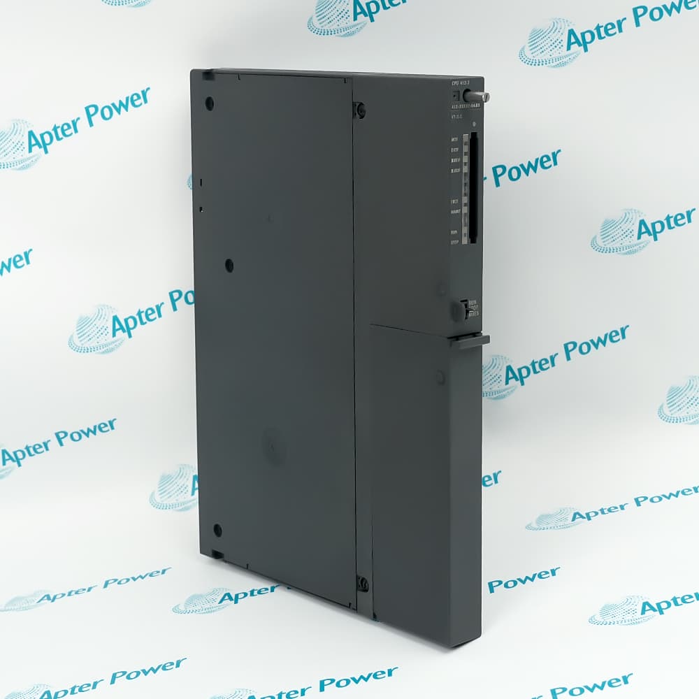
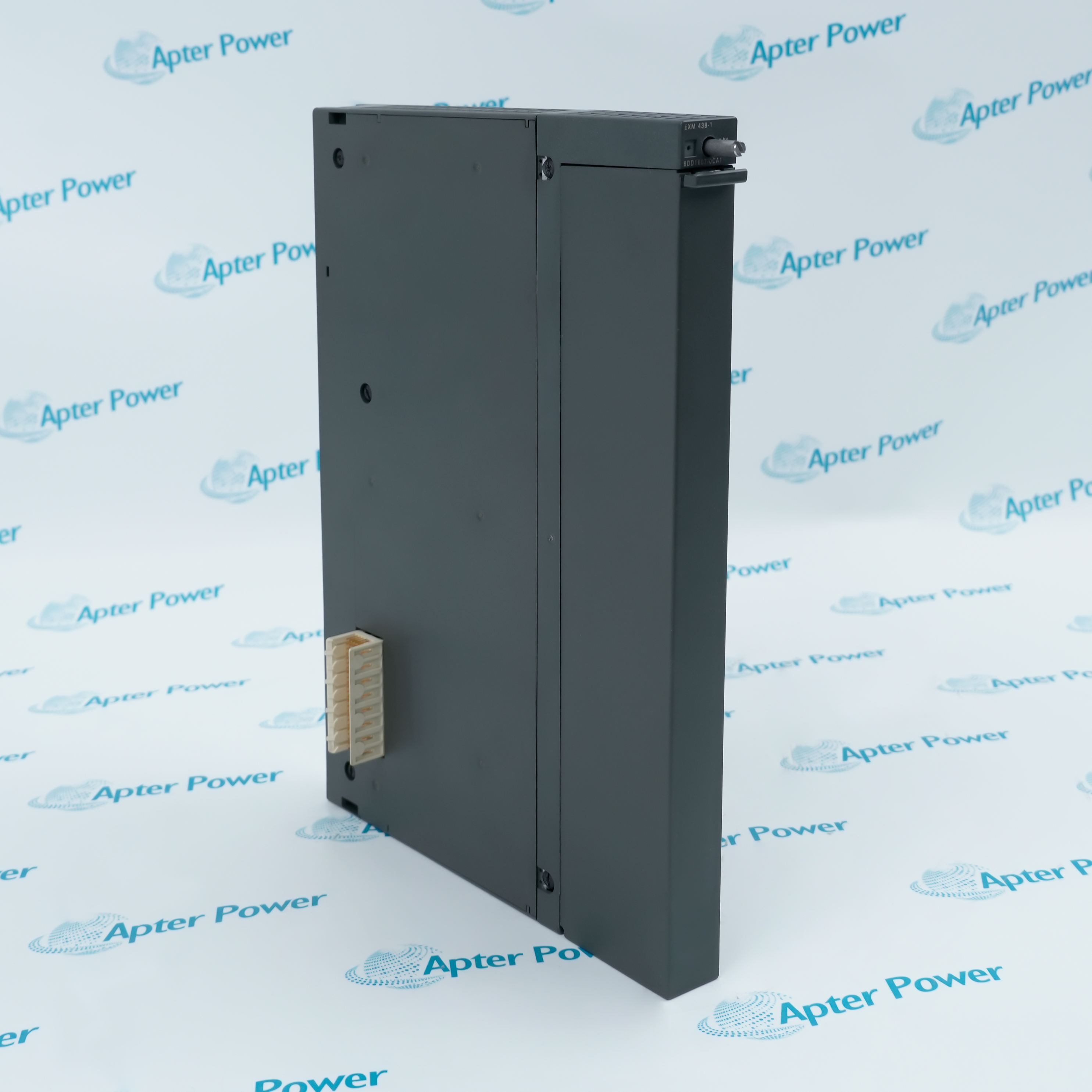
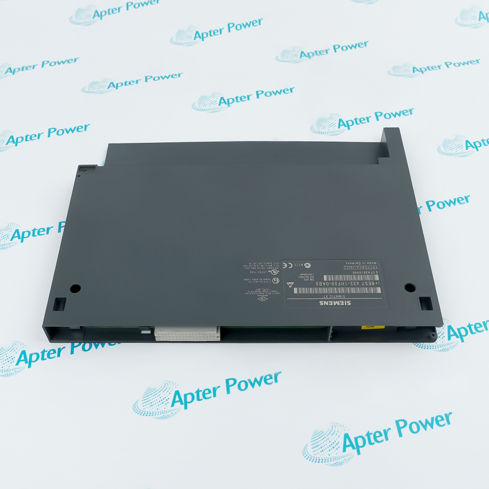
Features:
- Accepts voltage, current, resistance, RTD and thermocouple measurement types.
- Converts analog values at 16-bit resolution for the S7-400 CPU.
- Provides configurable diagnostics, limit alarms and end-of-cycle interrupts.
Channel-pair organization determines which inputs remain available for each measurement method.
The analog section is separated from the CPU while sharing a common electrical reference across its channels.
External 24 V loading depends on whether 6ES7431-7QH00-0AB0 supplies two-wire current transducers.
The Siemens 6ES7431-7QH00-0AB0 Analog Input Module may still be available for purchase and support from Apter Power beyond End-Of-Life (EOL) by the manufacturer (OEM).
Siemens 6ES7431-7QH00-0AB0 SM 431 Analog Input Module Manuals and Resources
Important Notice: Other accessories, manuals, cables, calibration data, software, etc. are not included with this equipment unless listed in the above stock item description. All prices are shown in USD.
Measurement-Position Assignment
- Direct inputs: Voltage, current and thermocouple ranges can use all 16 channels.
- Resistance inputs: RTD and resistance measurements are assigned to the eight even channels.
- Adjacent channel: The following odd channel carries the sensor-current connection for each resistance circuit.
- Configuration unit: Measuring-range modules and parameter settings are reviewed by channel pair.
Input-Cable Boundaries
- General reach: Applicable shielded analog leads can extend to 200 m.
- Low-level limit: Thermocouples and ranges up to 80 mV are limited to 50 m.
- Two-wire supply: The L+ path provides up to 50 mA for each powered transducer input.
- Isolation boundary: Channels share their analog reference although the analog section is isolated from the CPU.
Signal-Fault Reporting
- Diagnostic interrupt: Configured channel faults can be transferred to the controller program.
- Wire break: Monitoring is available for thermocouple, RTD and resistance circuits.
- Current exception: Current-loop wire break applies only to four-wire 4–20 mA measurement.
- Cycle reporting: End-of-cycle interrupts can synchronize processing with completed conversions.
Thermocouple Compensation Path
- RTD position: A reference-junction sensor is connected through channel 0.
- Reserved pair: Channels 0 and 1 are consumed by that compensation circuit.
- Compensated group: The measured junction temperature serves thermocouples on channels 2–15.
- Planning effect: Reference-junction use reduces the remaining direct measurement count by one pair.
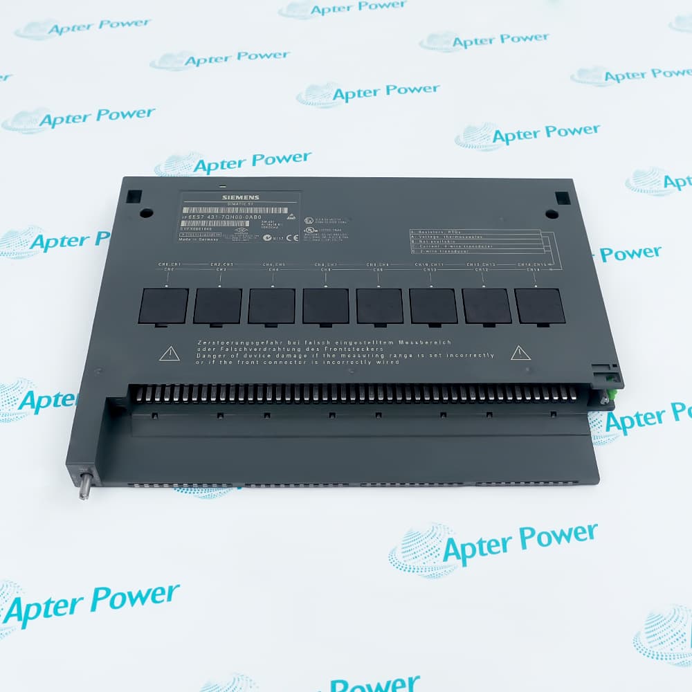
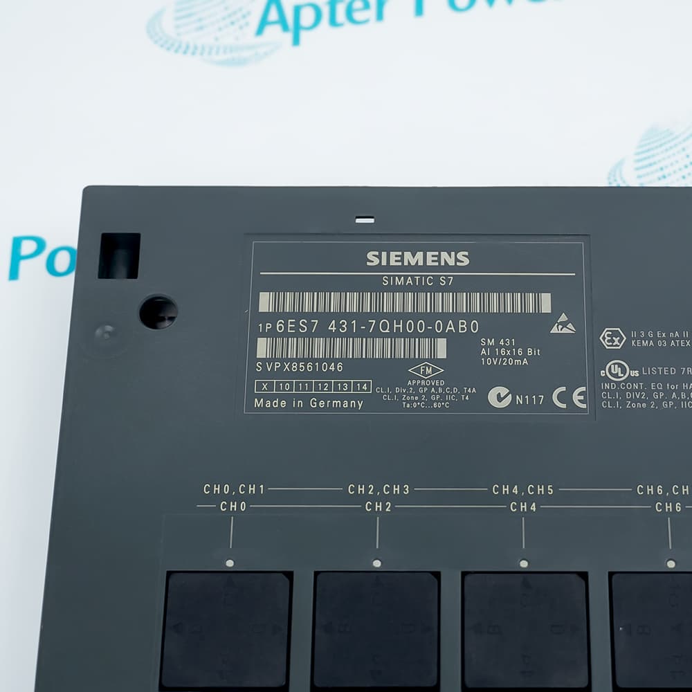

 6ES7431-7QH00-0AB0 Datasheet