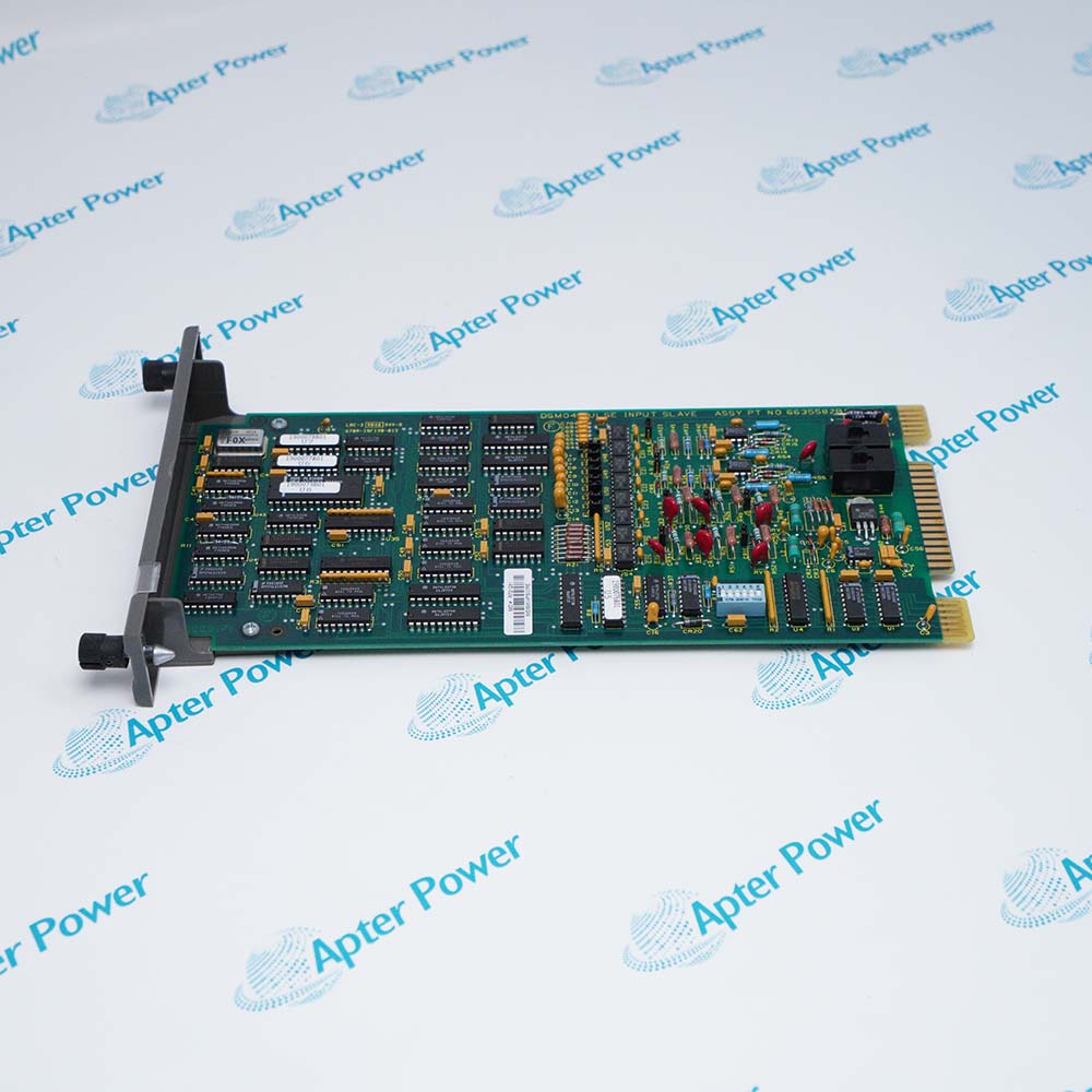
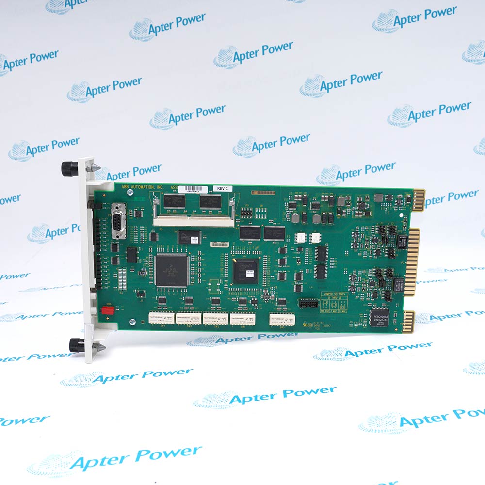
IPSYS01
IPSYS01
IPSYS01
IPSYS01
IPSYS01
IPSYS01
Ask our team:
  • Phone: +86 181 0690 9650
  • E-Mail sales1@apterpower.com
  • Lifecycle status

    Active / Available from OEM
    Apter Power matches IPSYS01 rail requirements with official power-system documentation and pre-shipment verification.

IPSYS01

/ 4.9
1001 reviews | Need a Specific Revision?
ABB IPSYS01 supplies the documented low-voltage system buses used by Harmony rack hardware in Modular Power System II.
In Stock
Ships by Wednesday, October 28
Fast Shipping Available
Get a quick price for IPSYS01
Quantity
*E-mail
Company
*Mobile
*Content
Upload (gif, jpg, jpeg, png, bmp, doc, docx, xls, xlsx, ppt, pdf, csv)

Technical specifications for IPSYS01

  • Manufacturer:
    ABB
  • Part Number:
    IPSYS01
  • Product Family:
    ABB Bailey
  • Product Type:
    System Power Module
  • Stock:
    1
  • System outputs:
    5 VDC, +15 VDC, -15 VDC and 24 VDC
  • Heat dissipation:
    175 W
  • Hold-up time:
    20 ms following loss of power
  • Line regulation:
    ±0.5% of nominal output over the input range
  • Load sharing:
    Current shared within 5% at full load
  • Weight:
    2.55 kg
  • Estimated shipping dimensions:
    21.84x4.83x44.45cm
  • Tariff Code:
    Please confirm the destination before shipping
  • Country of origin:
    Sweden
  • Place of shipment:
    Xiamen,Fujian,China
By purchasing this item, you agree to the Terms & Conditions, ApterPower is not an authorized distributor for listed manufacturers or tradenames and therefore the manufacturer's warranty does not apply. All our products come with ApterPower's 1-year warranty.

More Information

Overview Manuals Specifications DC Outputs Chassis Planning

Features:

  • System-power outputs for Harmony rack modules
  • Documented load sharing and 20 ms hold-up behavior
  • Thermal planning anchored by 175 W heat dissipation
IPSYS01 supplies the low-voltage rails needed by the rack portion of Modular Power System II.

Its operating role combines regulated system outputs with load-sharing behavior inside the power architecture.

Selection must consider chassis airflow, power demand, and redundancy together rather than treating the module as an isolated supply.

Availability of IPSYS01 is subject to Apter Power's current inventory and sourcing confirmation.
IPSYS01 Manuals, Datasheets, Links Important Notice: Other accessories, manuals, cables, calibration data, software, etc. are not included with this equipment unless listed in the above stock item description. All prices are shown in USD.
ABB IPSYS01 System Power Module Specs

General

  • ManufacturerABB
  • ModelIPSYS01
  • ConditionNew Original ready stock
  • Product FamilyABB Bailey
Important Notice: Other accessories, manuals, cables, calibration data, software, etc. are not included with this equipment unless listed in the above stock item description. All prices are shown in USD.

System-bus assignment

  • Logic rail: provide the documented 5 VDC bus
  • Analog rails: retain the positive and negative 15 VDC paths
  • Auxiliary rail: include the documented 24 VDC system output
  • Load test: verify every rail at the actual operating demand

MPSII integration

  • Mounting: confirm the correct power-module chassis
  • Load sharing: review current balance across installed modules
  • Hold-up: include the 20 ms specification in power-loss analysis
  • Cooling: account for the published module heat dissipation

Engineering acceptance

  • Demand: calculate connected rack-module load
  • Redundancy: document the intended module arrangement
  • Airflow: check enclosure temperature and fan service
  • Commissioning: record output rails and load-share behavior
Description
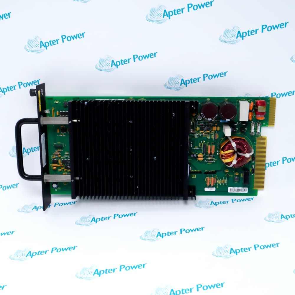
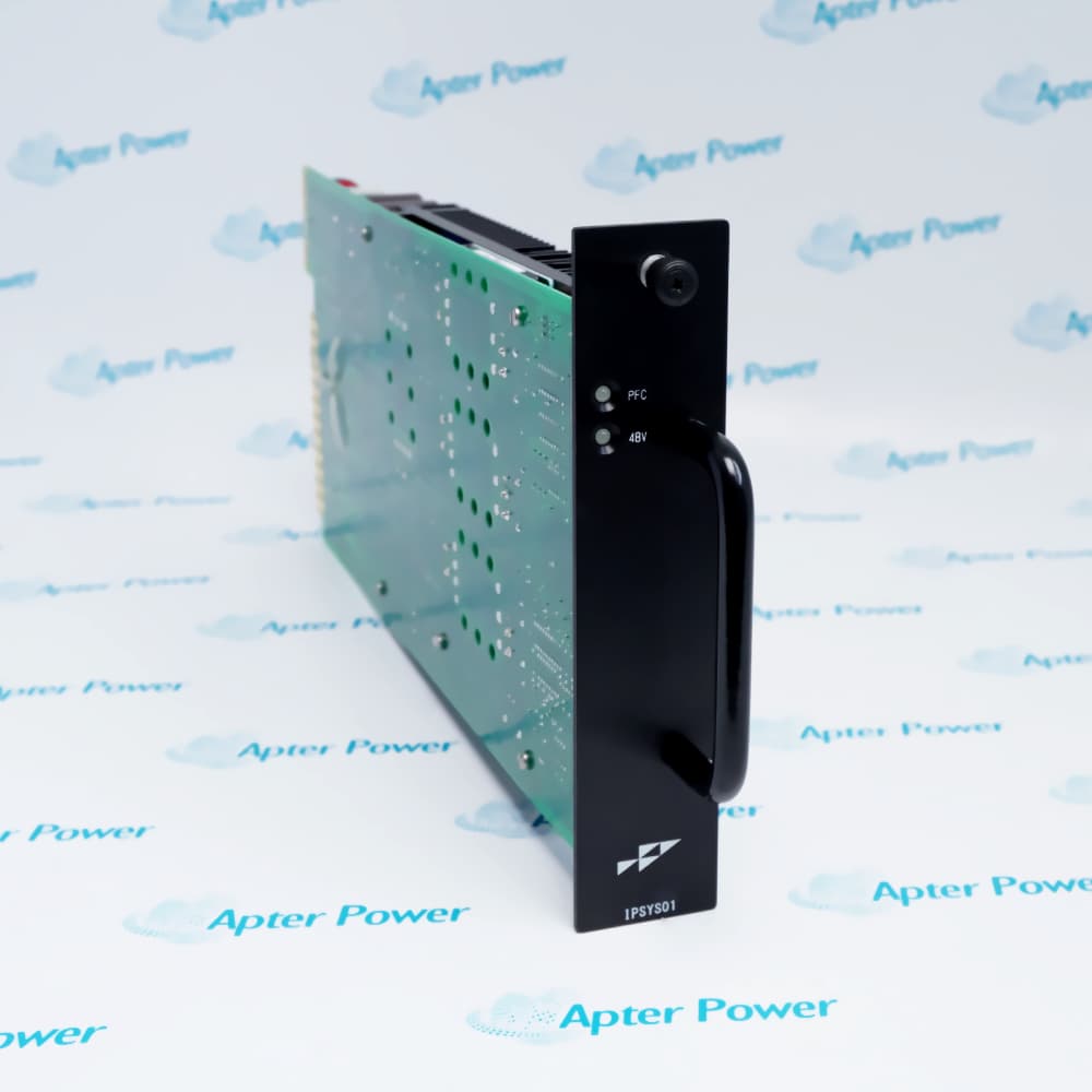
IPSYS01 is ABB's system power module for Modular Power System II. The official data sheet assigns it to the 5 VDC, positive 15 VDC, negative 15 VDC, and 24 VDC system-power rails used by Harmony rack modules.

At full operation, IPSYS01 is documented with 175 W heat dissipation, 20 ms hold-up following loss of input power, and regulated output behavior within the MPSII load-sharing architecture. The module weighs 2.55 kg.

For installation of IPSYS01, review the MPSII chassis, airflow, input source, bus loading, and redundancy plan as one power system. A successful change must verify all system rails under load rather than checking only module power-up indication.
Alternative Names
ABB IPSYS01 IPSYS 01 IPSYS-01 ABB Bailey IPSYS01 MPS II IPSYS01
Technical notes
Calculate cabinet heat and bus loading before deploying IPSYS01. ABB assigns this module to 5 VDC, +15 VDC, -15 VDC, and 24 VDC system rails, specifies 175 W heat dissipation and 20 ms hold-up, and supports load sharing; verify airflow, chassis position, redundancy, and every rail under operating load.
Exceptional Service

Our Mission

  • 100% Satisfaction

    We believe expertise is priceless. With over 20 years of experience, and top engineers on staff, we can help you solve or avoid problems that threaten your business.
  • Trust Guaranteed

    Not only do we have a vast inventory, our team makes sure every piece of equipment is in working condition. Your purchases are also backed by our Warranty.
  • Expertise

    Time is money, especially when your equipment is down. We work quickly to get your equipment on its way so you can get it back up and running.

FAQS

The following is a list of questions commonly asked by our customers. Please contact us if you have a question about our process that is not answered below.
If two IPSYS01 modules differ by more than the documented full-load sharing tolerance, what should engineers investigate?
ABB specifies current sharing within 5 percent from the highest-loaded to the lowest-loaded module; review chassis connections, module loading, and the approved redundancy arrangement.
Why does the 20 ms hold-up value for IPSYS01 not by itself prove system ride-through?
The value describes module behavior after input loss; acceptance must also confirm that the connected rack load and every system rail remain within the application requirement.
How can IPSYS01 pass an unloaded voltage check but fail after rack modules are restored?
ABB defines regulated operation across the specified load range, so measure the 5 V, positive and negative 15 V, and 24 V rails under actual demand.
When analog functions misbehave but logic remains active, which IPSYS01 evidence helps isolate the power path?
Compare the positive and negative 15 V rails under load with the 5 V logic rail instead of treating the four outputs as one common condition.
If IPSYS01 output changes as its input moves within range, what regulation limit should acceptance use?
ABB specifies line regulation within plus or minus 0.5 percent of nominal output across the input-voltage range; investigate changes outside that boundary.
For a redundant IPSYS01 plan, which engineering records belong in the RFQ?
Include the power-module chassis, installed module count, rack-load calculation, input arrangement, airflow design, and the intended current-sharing configuration.

Product Browsing History