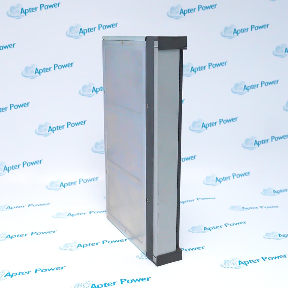
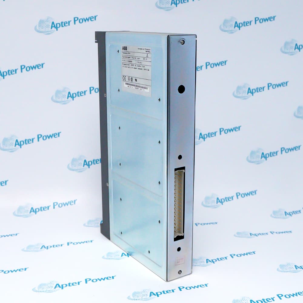
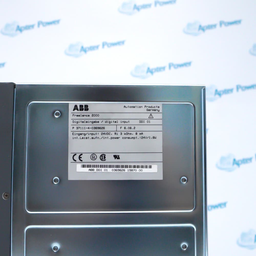
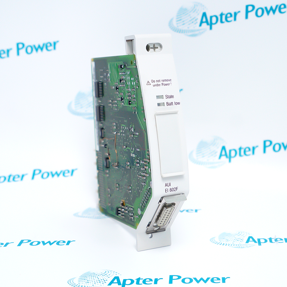
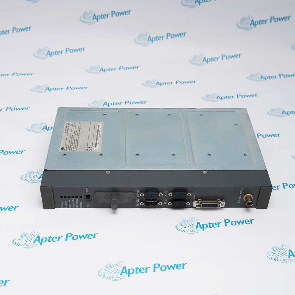
ABB DDI01 P3711-4-0369626
Ask our team:
  • Phone: +86 181 0690 9650
  • E-Mail sales1@apterpower.com
  • Lifecycle status

    Active / Available from OEM
    Current supply should be confirmed against the complete ABB order code, installed channel assignment and system- or field-powered input arrangement.

DDI01 P3711-4-0369626

/ 4.9
1001 reviews | Need a Specific Revision?
ABB DDI01 P3711-4-0369626 is a Freelance 2000 digital input module whose channel assignment and 24 V DC powering method must match the installed application.
In Stock
Ships by Thursday, October 29
Fast Shipping Available
Get a quick price for DDI01 P3711-4-0369626
Quantity
*E-mail
Company
*Mobile
*Content
Upload (gif, jpg, jpeg, png, bmp, doc, docx, xls, xlsx, ppt, pdf, csv)

Technical specifications for DDI01 P3711-4-0369626

  • Manufacturer:
    ABB
  • Part Number:
    DDI01 P3711-4-0369626
  • Product Family:
    ABB H&B Freelance 2000
  • Product Type:
    Freelance 2000 Digital Input Module
  • Stock:
    1
  • Module type:
    DDI01 digital input module
  • System family:
    Freelance 2000
  • Input reference:
    24 V DC digital input
  • Order code:
    P3711-4-0369626
  • Verification boundary:
    Channel map, commons and powering method
  • Weight:
    1.64 kg
  • Estimated shipping dimensions:
    4x18.5x30.8cm
  • Tariff Code:
    8537101190
  • Country of origin:
    Sweden
  • Place of shipment:
    Xiamen,Fujian,China
By purchasing this item, you agree to the Terms & Conditions, ApterPower is not an authorized distributor for listed manufacturers or tradenames and therefore the manufacturer's warranty does not apply. All our products come with ApterPower's 1-year warranty.

More Information

Overview Manuals Input Topologies Powering Schemes Channel Diagnosis Applications

Features:

  • Digital-input role: brings documented 24 Vdc field states into Freelance 2000.
  • Powering review: distinguishes system-powered and field-powered wiring.
  • Channel traceability: preserves the terminal and process-signal map.
The complete DDI01 and P3711-4-0369626 identity should be retained in purchasing, receiving and maintenance records.

The configured channel grouping, 24 Vdc commons and redundancy wiring must be read from the installed cabinet rather than inferred from a generic module description.

A controlled exchange proves every input from the field contact through the module and controller indication before the system is returned to service.

Apter Power can help review the channel map and complete ABB identity for DDI01 P3711-4-0369626 enquiries.
ABB DDI01 P3711-4-0369626 Freelance 2000 Digital Input Module Manuals,Datasheets,LinkImportant Notice: An official ABB English Freelance 2000 manual covers DDI01 operation, but the full order-code mapping requires installed-label confirmation before a branded PDF is attached.
  • Sixteen-channel layout: the Contrans I backplane maps one 16-point DDI01 input set through the documented slot and connector arrangement.
  • Thirty-two-channel layout: supported module/backplane combinations add a second channel bank, so the cabinet map must distinguish the base points from the additional inputs.
  • Failure-signalling layout: ABB documents a 16-channel arrangement with a separate failure-signalling path rather than treating that path as an ordinary process input.
  • Redundant layout: two DDI01 modules can be wired to the same 16-channel field set, making redundancy a defined architecture rather than an automatic property of one module.
  • System-powered inputs: use the backplane's +24 Vdc and 0 V distribution to establish the field-contact circuit shown in the ABB functional drawing.
  • Field-powered inputs: use an external +24 Vdc source and return, moving the supply boundary outside the backplane.
  • Reference routing: the chosen scheme determines where the common and return conductors terminate; the two schemes are not interchangeable wiring conventions.
  • State consequence: applying the wrong power-reference assumption can leave an input inactive or present a valid voltage at the wrong controller point.
  • Single-point mismatch: when one field contact disagrees with its controller indication, the terminal route and channel assignment are the first fault boundary.
  • Bank-level loss: several adjacent points failing together directs attention to the shared connector, backplane path or 24 Vdc reference rather than unrelated field devices.
  • Failure signal present: on the documented signalling configuration, the failure path must be interpreted separately from the process-state channels.
  • Redundant disagreement: different states from paired DDI01 paths separate a module or backplane fault from a field contact common to both paths.
  • Sixteen-point acquisition: discrete contact monitoring through a documented single-bank DDI01 arrangement.
  • Thirty-two-point acquisition: higher-density digital input mapping with a second channel bank.
  • Failure-signalling inputs: process-state acquisition where ABB's dedicated failure path is part of the cabinet design.
  • Redundant digital inputs: paired-module monitoring for installations wired to ABB's documented redundant topology.
Description
DDI01 P3711-4-0369626 is an ABB Freelance 2000 digital input module identified by the DDI01 designation and complete order code. The installed channel map must remain with that exact identity during sourcing and service.

The input arrangement for DDI01 P3711-4-0369626 can depend on the configured channel grouping and whether the signals are system powered or field powered. Confirm the terminal assignment, commons, 24 Vdc distribution and any redundancy arrangement from the running cabinet documentation.

Before exchanging DDI01 P3711-4-0369626, record live input states and label every field conductor. After replacement, verify each channel against the field device and the controller indication rather than accepting the module from a healthy status indication alone.
Alternative Names
DDI01 P3711-4-0369626 DDI01 P3711-4-0369626 ABB DDI01 ABB P3711-4-0369626 ABB DDI01 P3711-4-0369626
Technical notes
DDI01 P3711-4-0369626 belongs to a 24 Vdc digital-input boundary whose channel grouping, commons and powering method are installation dependent. Preserve the exact terminal map and live-state baseline before removal; stop work if the received order code or connector arrangement differs. A shifted channel map can produce valid but incorrect process indications.
Exceptional Service

Our Mission

  • 100% Satisfaction

    We believe expertise is priceless. With over 20 years of experience, and top engineers on staff, we can help you solve or avoid problems that threaten your business.
  • Trust Guaranteed

    Not only do we have a vast inventory, our team makes sure every piece of equipment is in working condition. Your purchases are also backed by our Warranty.
  • Expertise

    Time is money, especially when your equipment is down. We work quickly to get your equipment on its way so you can get it back up and running.

FAQS

The following is a list of questions commonly asked by our customers. Please contact us if you have a question about our process that is not answered below.
How should maintenance distinguish the wiring options for DDI01 P3711-4-0369626?
Use the installed Freelance 2000 drawings to identify channel grouping, commons and whether each input group is system powered or field powered.
What must be captured before removing DDI01 P3711-4-0369626?
Capture the complete terminal map, normal live states, 24 Vdc source and return, redundancy references and controller channel assignments.
When should receiving hold DDI01 P3711-4-0369626?
Hold the unit if the order code, connector arrangement, physical condition or documented channel boundary differs from the installed module.
Why is a healthy module indication insufficient for DDI01 P3711-4-0369626?
A healthy status does not prove that field conductors and channel assignments were restored correctly; each process input must be functionally checked.
How should field-powered inputs be tested on DDI01 P3711-4-0369626?
Verify the external 24 Vdc source and polarity, operate the field contact under the approved test plan, and confirm the correct controller point changes state.
What releases DDI01 P3711-4-0369626 after replacement?
Every expected input must follow its field device without shifted, stuck or false states, and the controller diagnostics must remain normal.