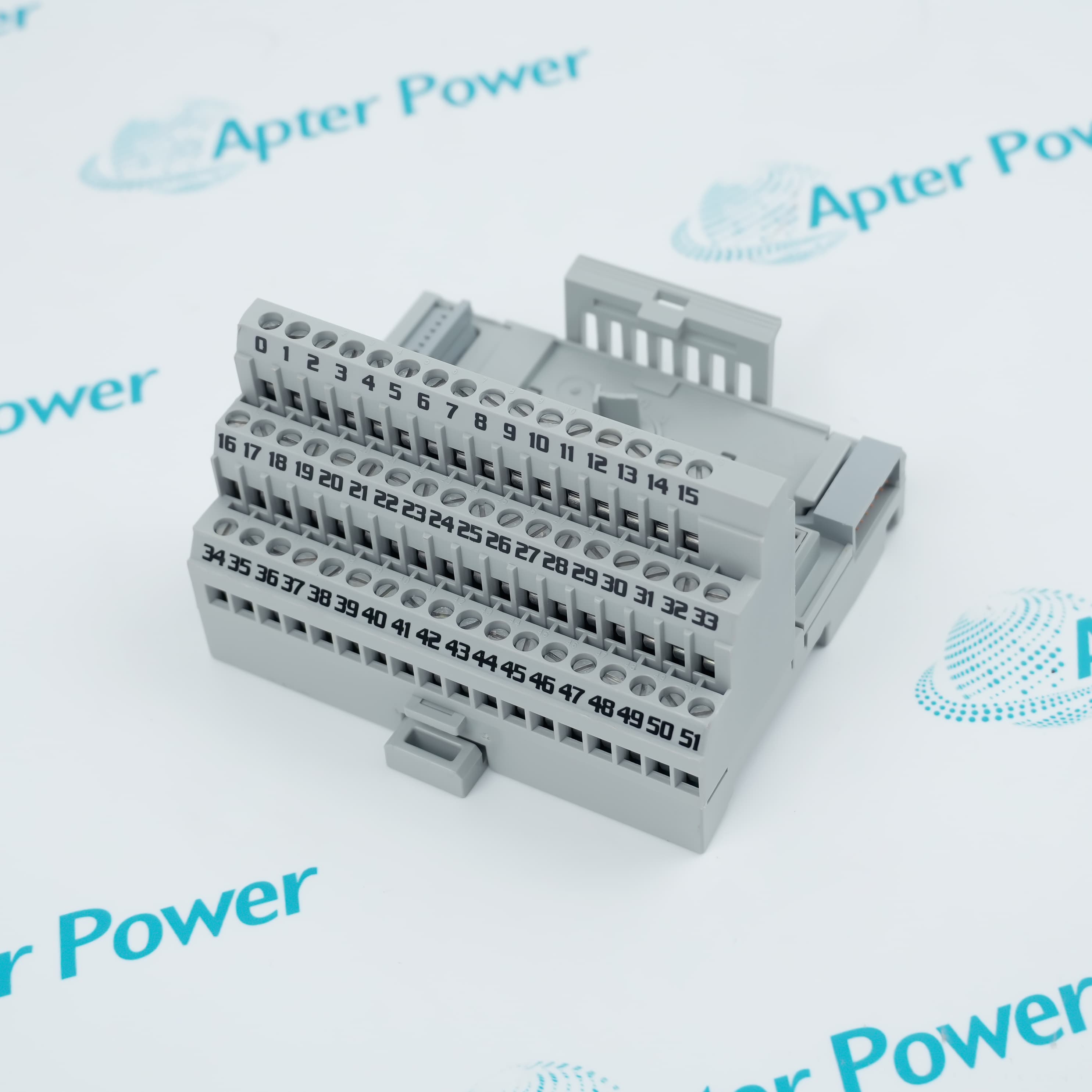
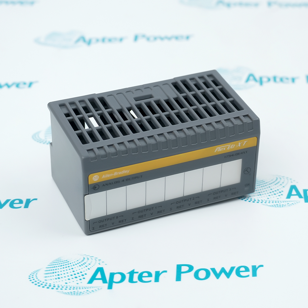
1794-TB3S
1794-TB3S
1794-TB3S
1794-TB3S
1794-TB3S
1794-TB3S
Ask our team:
  • Phone: +86 181 0690 9650
  • E-Mail sales1@apterpower.com
  • Lifecycle status

    Active / Available from OEM
    Apter Power supplies verified spring-terminal hardware with responsive service, detailed condition checks, and dependable sourcing coordination.

1794-TB3S

/ 4.9
1001 reviews | Need a Specific Revision?
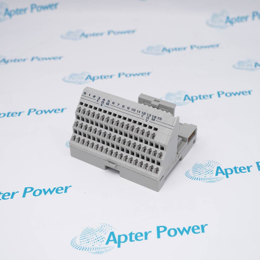
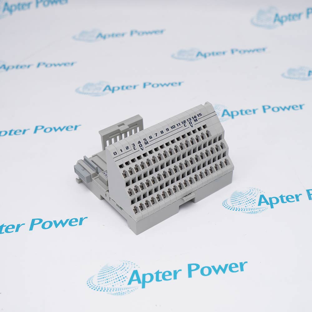
Allen-Bradley 1794-TB3S is a 3-wire spring-clamp FLEX I/O terminal base for fast field termination and modular Flexbus distribution.
In Stock
Ships by Wednesday, October 28
Fast Shipping Available
Get a quick price for 1794-TB3S
Quantity
*E-mail
Company
*Mobile
*Content
Upload (gif, jpg, jpeg, png, bmp, doc, docx, xls, xlsx, ppt, pdf, csv)

Technical specifications for 1794-TB3S

  • Manufacturer:
    Allen-Bradley
  • Part Number:
    1794-TB3S
  • Product Family:
    Flex I/O
  • Product Type:
    FLEX I/O 3-Wire Spring-Clamp Terminal Base
  • Stock:
    1
  • Termination:
    Spring clamp
  • I/O terminals:
    16
  • Common terminals:
    18
  • +V terminals:
    18
  • V/COM capacity:
    125 V AC/DC, 10 A maximum
  • Wire size:
    0.34...3.3 mm2, 22...12 AWG
  • Operating temperature:
    -20...+70 °C
  • Relative humidity:
    5...95% noncondensing
  • Mounting:
    DIN rail
  • Estimated shipping dimensions:
    9.4 x 9.4 x 6.9 cm
  • Tariff Code:
    8537101190
  • Country of origin:
    Singapore
  • Place of shipment:
    Xiamen,Fujian,China
By purchasing this item, you agree to the Terms & Conditions, ApterPower is not an authorized distributor for listed manufacturers or tradenames and therefore the manufacturer's warranty does not apply. All our products come with ApterPower's 1-year warranty.

More Information

Overview Manuals Spring Wiring Base Match Station Recovery Product Applications

Features:

  • Spring-clamp service: field conductors retained without terminal-screw torque
  • Three-wire rows: I/O, common, and +V distribution in one base
  • Modular backplane: DIN-rail mounting with Flexbus continuation
1794-TB3S provides spring-clamp field termination beneath compatible FLEX I/O modules.

Its main service distinction is the conductor-retention method; electrical limits still come from the module and station design.

Acceptance should document module pairing, keying, wire preparation, retention results, V/COM loading, and base order.

Apter Power can coordinate official-document review, quotation, and sourcing support for 1794-TB3S.
1794-TB3S FLEX I/O 3-Wire Spring-Clamp Terminal Base Manuals, Datasheets, Links Important Notice: Other accessories, manuals, cables, calibration data, software, etc. are not included with this equipment unless listed in the above stock item description. All prices are shown in USD.
  • Wire preparation: apply the documented conductor size and strip length.
  • Insertion: seat the conductor fully with no exposed copper or loose strands.
  • Retention: perform a controlled tug test after each serviced connection.
  • Exact module: use the official installation instructions to approve the base.
  • Keyswitch: preserve the module-specific position during replacement.
  • Electrical limits: apply the required voltage, current, and isolation boundaries.
  • De-energize: remove station power before opening the Flexbus connection.
  • Sequence record: preserve the order of every downstream base and module.
  • Final check: verify communication and field status across the restored station.
  • Repeated panel service: use spring-clamp connections where approved module pairing permits.
  • Three-wire sensors: distribute signal, common, and supply in a remote station.
  • DIN-rail I/O: continue the FLEX I/O backplane through adjacent bases.
Description
1794-TB3S is a spring-clamp FLEX I/O terminal base with sixteen I/O points and separate common and +V distribution rows. It joins adjacent DIN-rail bases to carry Flexbus through the remote I/O station.

Unlike the cage-clamp version, 1794-TB3S retains conductors by spring pressure and does not use a field-terminal torque step. Reliable service still depends on approved wire size, clean stripping, full insertion, labeling, and a controlled retention test.

Selection of 1794-TB3S must start with an official compatibility listing for the installed module. Confirm the key position, field voltage, V/COM load, isolation boundary, grounding, and effect on downstream Flexbus before replacing a base.
Revisions

Revision Part #

Also known as

1794-TB3S Series A
1794-TB3S/A, Series A
Alternative Names
Allen-Bradley FLEX I/O TB3S Rockwell 1794 TB3S Spring Base 1794TB3S three-wire terminal unit FLEX I/O quick-wiring base
Technical notes
Spring pressure on 1794-TB3S removes the screw-torque step but not the need for correct conductor preparation. Use the documented strip length and wire size, confirm full insertion with a controlled tug test, and de-energize the complete Flexbus station before disturbing the base or its downstream connection.
Exceptional Service

Our Mission

  • 100% Satisfaction

    We believe expertise is priceless. With over 20 years of experience, and top engineers on staff, we can help you solve or avoid problems that threaten your business.
  • Trust Guaranteed

    Not only do we have a vast inventory, our team makes sure every piece of equipment is in working condition. Your purchases are also backed by our Warranty.
  • Expertise

    Time is money, especially when your equipment is down. We work quickly to get your equipment on its way so you can get it back up and running.

FAQS

The following is a list of questions commonly asked by our customers. Please contact us if you have a question about our process that is not answered below.
Why does 1794-TB3S not use the cage-clamp torque specification?
Its terminals retain conductors by spring pressure, so service quality is controlled by wire size, strip length, full insertion, and retention rather than screw torque.
What should be checked when a conductor pulls out of 1794-TB3S?
Inspect the approved wire size, strip length, damaged strands, ferrule suitability, insertion depth, terminal condition, and whether the correct release method was used.
Can 1794-TB3S replace a cage-clamp base without project review?
No. Confirm the exact module listing, key position, terminal map, conductor method, electrical limits, labels, and maintenance procedure before changing base style.
Why might downstream modules fault after 1794-TB3S is serviced?
The base also carries Flexbus, so incomplete mechanical engagement, changed station order, damaged connectors, or power restoration problems can interrupt modules to the right.
How should the V/COM path on 1794-TB3S be protected?
Calculate the aggregate load and coordinate module limits, conductors, terminals, branch protection, and local electrical requirements within the official base boundary.
What evidence should accompany a 1794-TB3S purchase?
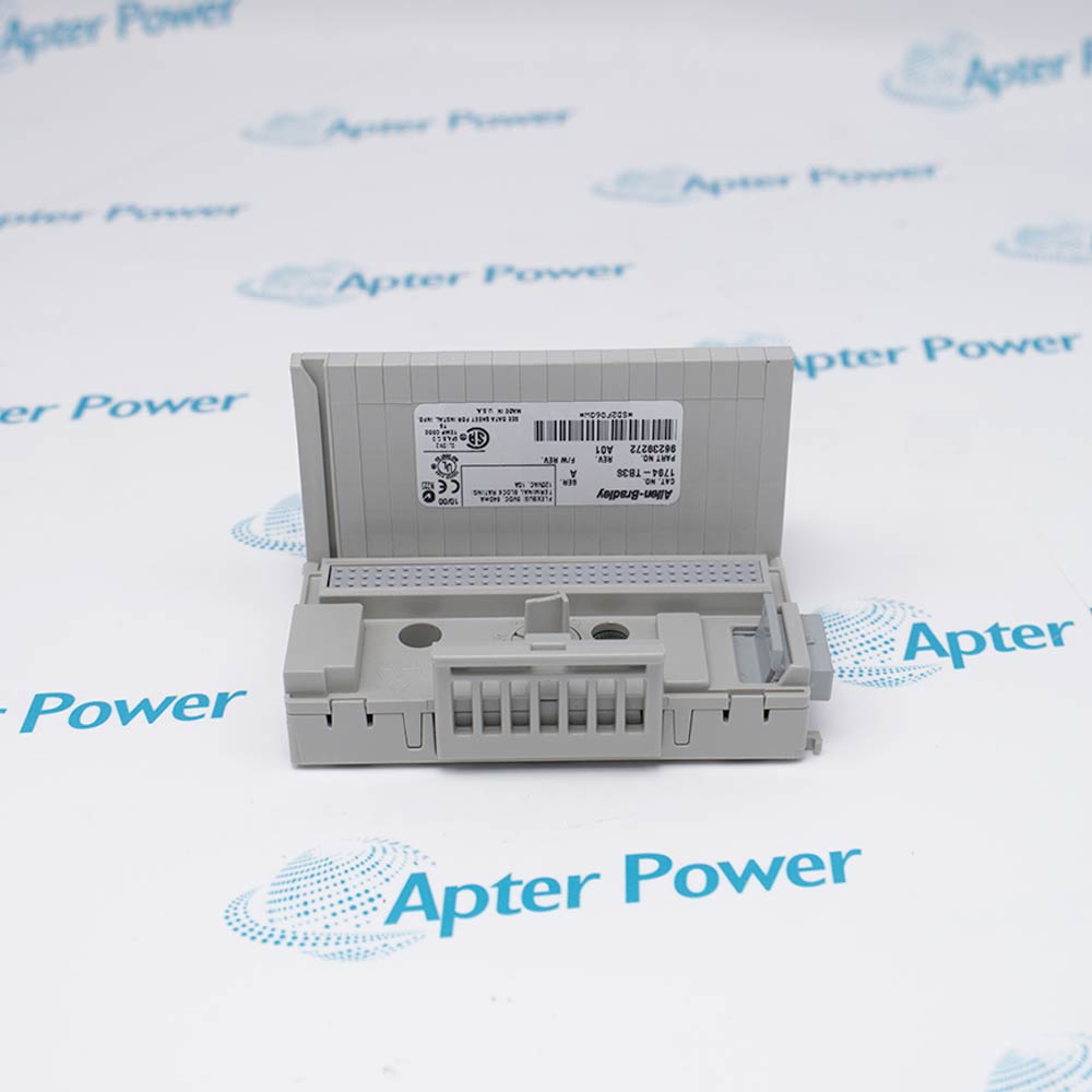
Provide full nameplates, Series, spring-terminal close-ups, latch and bus-connector photos, intended module, condition, quantity, destination, and required date.

Product Browsing History