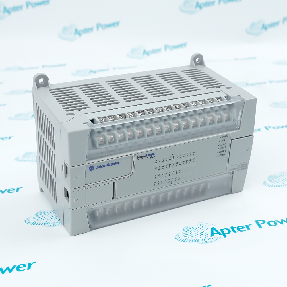
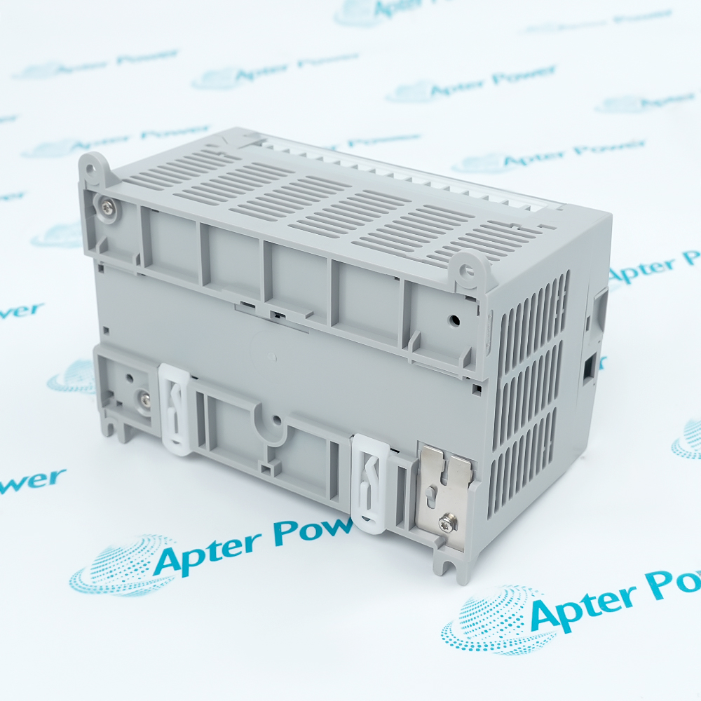
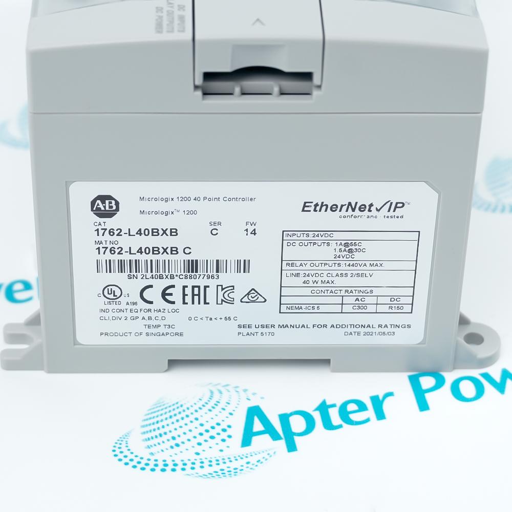
AB 1762-L40BXB
AB 1762-L40BXB
AB 1762-L40BXB
AB 1762-L40BXB
AB 1762-L40BXB
AB 1762-L40BXB
Ask our team:
  • Phone: +86 181 0690 9650
  • E-Mail sales1@apterpower.com
  • Lifecycle status

    Discontinued
    Discontinued date: 2021-08-25
    Replacement category: Engineering Replacement

1762-L40BXB

/ 4.9
1001 reviews | Need a Specific Revision?
Allen-Bradley 1762-L40BXB is a 24 V DC MicroLogix 1200 controller with 24 DC inputs and 16 mixed relay and FET outputs.
In Stock
Ships by Thursday, October 29
Fast Shipping Available
Get a quick price for 1762-L40BXB
Quantity
*E-mail
Company
*Mobile
*Content
Upload (gif, jpg, jpeg, png, bmp, doc, docx, xls, xlsx, ppt, pdf, csv)

Technical specifications for 1762-L40BXB

  • Manufacturer:
    Allen-Bradley
  • Part Number:
    1762-L40BXB
  • Product Family:
    MicroLogix
  • Product Type:
    MicroLogix 1200 40-Point Programmable Controller
  • Stock:
    1
  • Power Supply:
    24 V DC, -15% to +10%
  • User Memory:
    6 KB
  • Inputs:
    20 standard 24 V DC and 4 fast 24 V DC
  • Outputs:
    8 relay, 7 standard 24 V DC FET and 1 fast 24 V DC FET
  • Communication:
    DF1, DH-485, Modbus RTU and ASCII
  • Communication Interface:
    RS-232C
  • Expansion Capacity:
    Up to 6 modules
  • Power Supply Inrush:
    15 A for 30 ms
  • Heat Dissipation:
    27.9 W plus 0.3 × system loading
  • Fast Output Function:
    PTO or PWM on Output 2
  • Fast Input Frequency:
    Up to 20 kHz, filter dependent
  • Operating Temperature:
    0–55 °C
  • Storage Temperature:
    -40–85 °C
  • Operating Humidity:
    5–95%, non-condensing
  • Dimensions:
    16.0 × 9.0 × 8.7 cm
  • Weight:
    0.6 kg
  • Tariff Code:
    8537101190
  • Country of origin:
    USA
  • Place of shipment:
    Xiamen,Fujian,China
By purchasing this item, you agree to the Terms & Conditions, ApterPower is not an authorized distributor for listed manufacturers or tradenames and therefore the manufacturer's warranty does not apply. All our products come with ApterPower's 1-year warranty.

More Information

Overview Manuals Output behavior Serial links System loading Application
  • MicroLogix 1200 controller with 24 DC inputs and 16 mixed relay/FET outputs
  • Output 2 supports high-speed pulse-train or pulse-width-modulation operation
  • Channel 0 supports DF1, DH-485, Modbus RTU and ASCII communication

1762-L40BXB is an Allen-Bradley 24 V DC MicroLogix 1200 controller that integrates forty discrete I/O points with serial communication and expansion capability.

Its mixed output architecture combines isolated relay switching with standard and high-speed sourcing FET functions, while the configurable RS-232 channel connects programming, operator and serial network devices.

Before replacement, preserve the complete controller project and verify Series and firmware, supply and system loading, terminal commons, load type, expansion modules, communication protocol and all high-speed I/O assignments.

Availability, condition, price, and shipping time for 1762-L40BXB are confirmed during quotation.

Allen-Bradley 1762-L40BXB MicroLogix Controller Manuals, Datasheets, Links

Important Notice: Other accessories, manuals, cables, calibration data, software, etc. are not included with this equipment unless listed in the above stock item description. All prices are shown in USD.

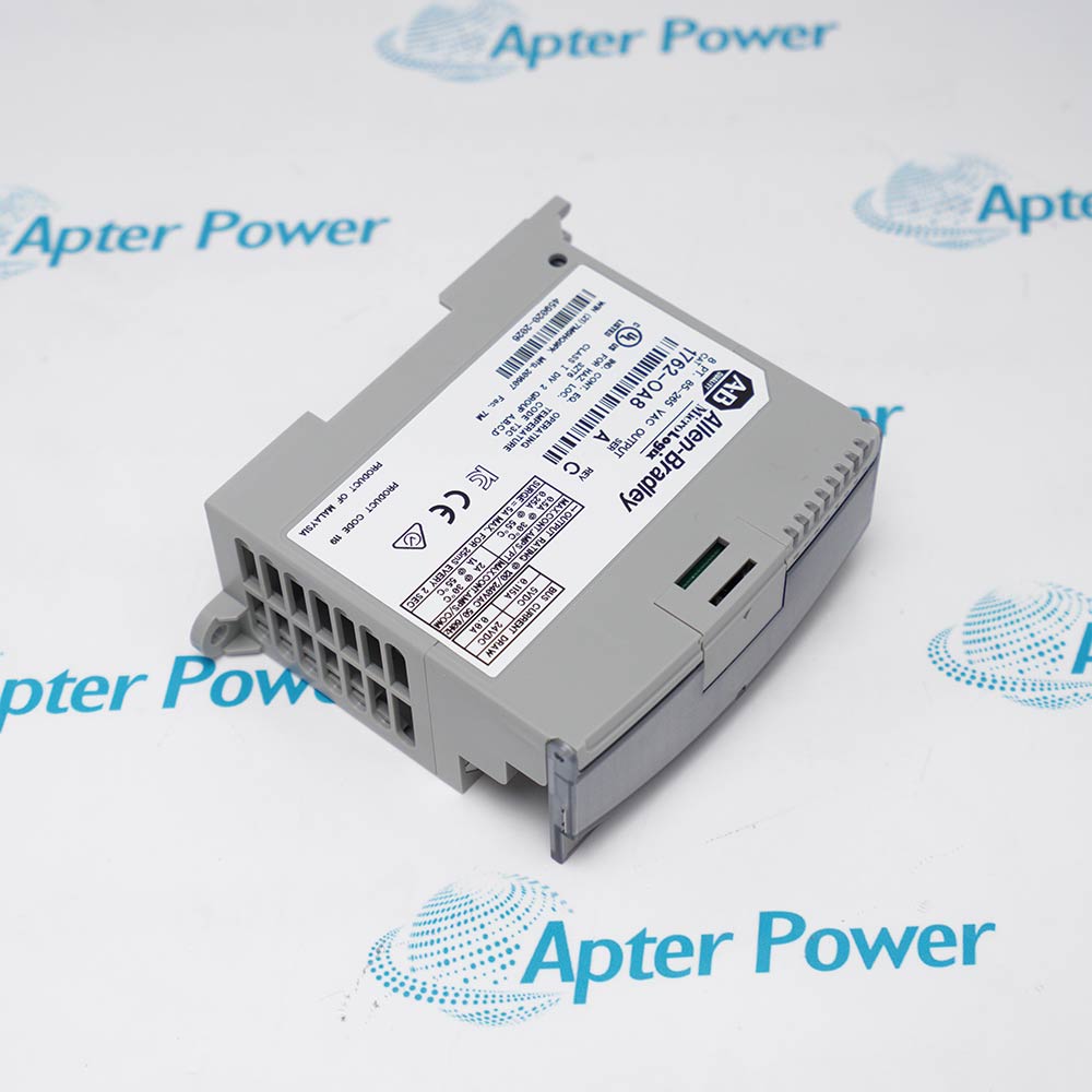
  • Eight relay outputs switch isolated AC or DC loads within their contact ratings
  • Seven standard FET outputs provide 24 V DC sourcing operation
  • Output 2 can operate as a normal FET output or provide PTO/PWM pulses
  • Channel 0 provides the controller’s RS-232C connection
  • Supported operating modes include DF1, DH-485, Modbus RTU and ASCII
  • Protocol, addressing and cable pinout must match the connected network or device
  • Up to six expansion modules are supported when the calculated bus load remains valid
  • Both 5 V and 24 V expansion-bus current totals are included in the worksheet
  • Enclosure heat calculations use the controller base dissipation plus system loading
  • Compact machine control using mixed relay and 24 V DC solid-state outputs
  • High-speed counting and PTO/PWM control for supported motion or pulse applications
  • Serial integration with DF1, DH-485, Modbus RTU or ASCII devices
Description
1762-L40BXB is an Allen-Bradley MicroLogix 1200 40-point programmable controller for compact machine and equipment control.

It combines 20 standard and four fast 24 V DC inputs with eight relay, seven standard FET and one fast FET output, plus 6 KB of program memory, RS-232 communication and support for up to six expansion modules.

Before installation or replacement, confirm the Series C controller and matching firmware, power and system-loading budget, input and output commons, relay and FET load assignments, serial protocol, expansion modules and saved application.
Revisions

Revision Part #

Also known as

1762-L40BXB Ser C
1762-L40BXB/C, Series C, Rev C
Alternative Names
1762-L40BXB 1762 L40BXB 1762L40BXB Allen-Bradley 1762-L40BXB Allen Bradley 1762-L40BXB MicroLogix 1200 1762-L40BXB MicroLogix 1762-L40BXB
Technical notes
Allen-Bradley 1762-L40BXB requires a verified Series C project, 24 V DC power budget, relay/FET terminal map, expansion loading and Channel 0 protocol before replacement.
Exceptional Service

Our Mission

  • 100% Satisfaction

    We believe expertise is priceless. With over 20 years of experience, and top engineers on staff, we can help you solve or avoid problems that threaten your business.
  • Trust Guaranteed

    Not only do we have a vast inventory, our team makes sure every piece of equipment is in working condition. Your purchases are also backed by our Warranty.
  • Expertise

    Time is money, especially when your equipment is down. We work quickly to get your equipment on its way so you can get it back up and running.

FAQS

The following is a list of questions commonly asked by our customers. Please contact us if you have a question about our process that is not answered below.
What project checks are required before replacing Allen-Bradley 1762-L40BXB?
Back up the complete RSLogix 500 application and record the controller Series, firmware, channel configuration, I/O addressing, expansion modules and data-file usage. Confirm that the replacement can accept the saved project before disconnecting field wiring.
How should relay and FET loads be reassigned on Allen-Bradley 1762-L40BXB?
Preserve the original output type and group-common wiring for every load. Relay outputs suit isolated switching duties, while the 24 V DC FET outputs require the correct polarity and current limits; Output 2 also carries the controller’s high-speed PTO or PWM role.
Can expansion I/O be added to Allen-Bradley 1762-L40BXB based only on the six-module limit?
No. Use the MicroLogix system-loading worksheet to verify both 5 V and 24 V bus currents and total loading for the exact expansion set. A controller can remain under six modules and still exceed its allowable power budget.
What must be preserved when reconnecting serial devices to Allen-Bradley 1762-L40BXB?
Record the selected DF1, DH-485, Modbus RTU or ASCII mode, baud rate, node address, parity, handshaking, cable pinout and connected device role. Restore the same Channel 0 configuration unless the network design is intentionally changed.
Why can a load behave differently after an Allen-Bradley 1762-L40BXB replacement?
Check whether the load was moved between relay and FET terminals, whether the correct group common and 24 V DC polarity were restored, and whether Output 2 was configured for normal, PTO or PWM operation. Also compare the program’s output map with the terminal labels.
What power-supply conditions can prevent Allen-Bradley 1762-L40BXB from starting reliably?
Verify that the 24 V DC source remains within the documented tolerance at the controller, can supply the startup inrush without excessive voltage drop, and has the required Class 2 or SELV characteristics. Include connected expansion modules in the loading calculation.
How should the status indicators be used after restoring Allen-Bradley 1762-L40BXB?
Confirm POWER first, then verify RUN, FAULT, FORCE and COMM 0 against the intended operating state. If the controller does not enter Run mode, use the indicator pattern with the saved project and communications settings to separate power, application, hardware and serial-link faults.

Product Browsing History