Ask our team:
  • Phone: +86 181 0690 9650
  • E-Mail sales1@apterpower.com

1775-LX

/ 4.9
1001 reviews | Need a Specific Revision?
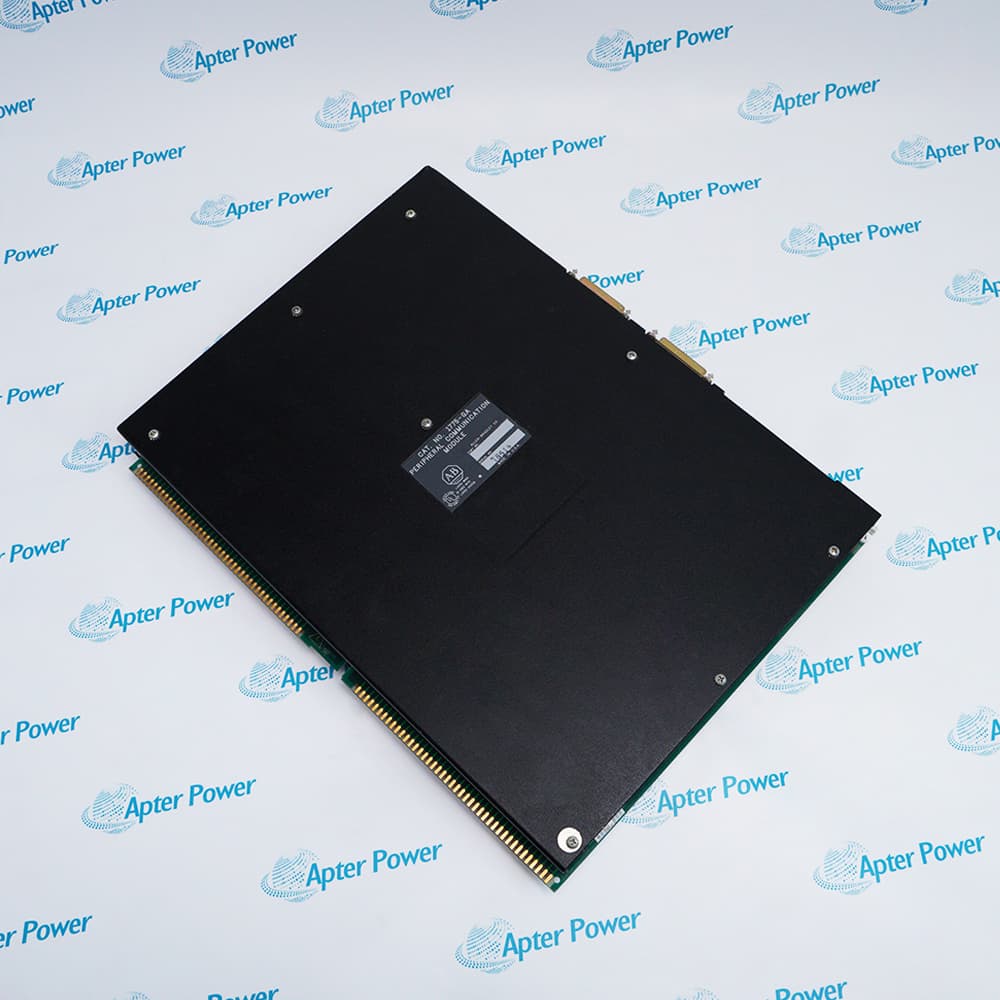
Allen-Bradley 1775-LX links PLC-3 processor chassis in a multi-chassis expansion system and reports expansion-bus parity faults through its EBUS PARITY ERROR indicator.
In Stock
Ships by Wednesday, October 28
Fast Shipping Available
Get a quick price for 1775-LX
Quantity
*E-mail
Company
*Mobile
*Content
Upload (gif, jpg, jpeg, png, bmp, doc, docx, xls, xlsx, ppt, pdf, csv)

Technical specifications for 1775-LX

  • Manufacturer:
    Allen-Bradley
  • Part Number:
    1775-LX
  • Product Family:
    PLC-3
  • Product Type:
    PLC-3 Expansion Module
  • Stock:
    1
  • Function:
    Processor-chassis expansion-bus interface
  • Module Quantity:
    One per processor chassis
  • Maximum System Size:
    Four processor chassis
  • Expansion Cable Set:
    1775-CX
  • Distribution Panel:
    1775-CXD for three- and four-chassis systems
  • Terminators:
    1775-CXT for three-chassis systems
  • Diagnostic Indicator:
    EBUS PARITY ERROR
  • Dimensions:
    5.5 × 29.5 × 39.5 cm
  • Chassis Location:
    Single slot in a PLC-3 main or expansion chassis
  • Expansion Bus Connectors:
    Four 50-pin connectors labeled A, B, C, and D
  • Backplane Power Supply:
    +5 V and -15 V DC from the 1775-P1 through the chassis backplane
  • Backplane Current at 5 V DC:
    5 A
  • Backplane Current at -15 V DC:
    80 mA
  • Operating Temperature:
    0 to 60 °C
  • Storage Temperature:
    -40 to 85 °C
  • Relative Humidity:
    5% to 95%, noncondensing
  • Weight:
    2.5 kg
  • Tariff Code:
    8538900000
  • Country of origin:
    USA
  • Place of shipment:
    Xiamen, Fujian, China
By purchasing this item, you agree to the Terms & Conditions, ApterPower is not an authorized distributor for listed manufacturers or tradenames and therefore the manufacturer's warranty does not apply. All our products come with ApterPower's 1-year warranty.

More Information

Overview Manuals Expansion Topology Cabling Diagnostics Application
  • Coordinates PLC-3 processor chassis in two-, three-, or four-chassis expansion layouts
  • Match 1775-CX cables, the 1775-CXD panel, and 1775-CXT terminators to the installed topology
  • Trace parity faults by checking chassis order and every expansion-bus channel connection

1775-LX is installed once in each PLC-3 processor chassis that participates in the documented expansion-bus arrangement.

Two-, three-, and four-chassis layouts use different combinations of 1775-CX cables, the 1775-CXD panel, and 1775-CXT terminators.

Chassis order and every channel connection must be restored exactly because a topology error can appear as an expansion-bus parity fault.

Availability, condition, price, and shipping time for 1775-LX are confirmed during quotation.

Allen-Bradley 1775-LX PLC-3 Expansion Module Manuals, Datasheets, Links

Important Notice: Other accessories, manuals, cables, calibration data, software, etc. are not included with this equipment unless listed in the above stock item description. All prices are shown in USD.

  • PLC-3 expansion can include as many as four processor chassis.
  • One 1775-LX expansion module is installed in each processor chassis.
  • The required panel and terminators depend on whether the system has two, three, or four chassis.
  • 1775-CX cable sets connect the expansion modules and distribution panel.
  • The 1775-CXD panel is used in three- and four-chassis systems.
  • 1775-CXT terminators are documented for the three-chassis topology.
  • The EBUS PARITY ERROR indicator reports a transmission parity fault between expansion modules.
  • Cable seating, routing, panel ports, and terminators should be checked as one complete bus.
  • Chassis placement and every channel connection must be restored from the recorded topology.
  • Two-chassis PLC-3 systems using a direct documented expansion cable arrangement.
  • Three-chassis PLC-3 systems using the distribution panel and required terminators.
  • Four-chassis PLC-3 systems using the documented distribution-panel topology.
Description
Allen-Bradley 1775-LX is the PLC-3 expansion-bus module installed one per processor chassis in multi-chassis PLC-3 systems.

The official expansion architecture supports as many as four processor chassis using 1775-CX cable sets, with a 1775-CXD distribution panel and 1775-CXT terminators where required by chassis count.

Before replacement, document every chassis position, channel, cable, distribution-panel connection, terminator, and parity indication because topology varies between two-, three-, and four-chassis systems.
Alternative Names
1775-LX Allen-Bradley 1775-LX Allen Bradley 1775-LX PLC-3 1775-LX 1775-LX PLC-3 Expansion Module PLC-3 Expansion Module 1775-LX
Technical notes
1775-LX replacement requires mapping every PLC-3 chassis, 1775-CX cable, 1775-CXD panel port, and 1775-CXT terminator; topology errors can trigger parity faults despite a correct module.
Exceptional Service

Our Mission

  • 100% Satisfaction

    We believe expertise is priceless. With over 20 years of experience, and top engineers on staff, we can help you solve or avoid problems that threaten your business.
  • Trust Guaranteed

    Not only do we have a vast inventory, our team makes sure every piece of equipment is in working condition. Your purchases are also backed by our Warranty.
  • Expertise

    Time is money, especially when your equipment is down. We work quickly to get your equipment on its way so you can get it back up and running.

FAQS

The following is a list of questions commonly asked by our customers. Please contact us if you have a question about our process that is not answered below.
How can a buyer confirm Allen-Bradley 1775-LX for an existing PLC-3 expansion system?
Map the number of processor chassis, module positions, every 1775-CX cable, the 1775-CXD panel, and any 1775-CXT terminators before ordering.
What must be documented before disconnecting any cable from Allen-Bradley 1775-LX?
Record every processor-chassis position, expansion-module slot, cable-end label, channel connection, distribution-panel port, and terminator location so the topology can be reconstructed exactly.
Why can a replacement Allen-Bradley 1775-LX produce EBUS parity errors even when its catalog number is correct?
A crossed expansion channel, loose 1775-CX connection, incorrect 1775-CXD port, missing terminator, or wrong chassis sequence can corrupt communication across the expansion bus.
When is the 1775-CXD panel required with Allen-Bradley 1775-LX?
The expansion distribution panel is documented for three- and four-chassis PLC-3 systems.
What should be preserved before replacing Allen-Bradley 1775-LX?
Record chassis numbering, slot locations, all four-channel cable routes, distribution-panel ports, terminator locations, and current parity indications.
What does the EBUS PARITY ERROR indicator mean on Allen-Bradley 1775-LX?
It reports a parity error during transmission between expansion modules; inspect the complete bus topology and cables before returning the system to service.
When should Allen-Bradley 1775-LX troubleshooting include the entire PLC-3 expansion chain?
Inspect the full chain whenever a chassis disappears, parity faults recur, or communication changes after power cycling, because the fault may originate at another module, cable, panel, or terminator.