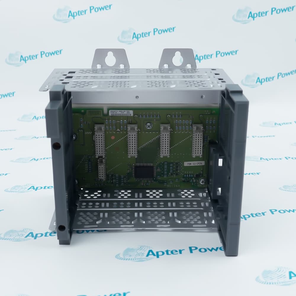
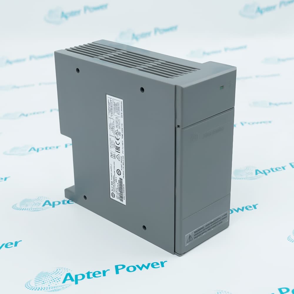
Features:
- Serves as the communication bridge between the logic control unit and the high-voltage power stage
- Integrates signal processing with power stage interface conversion capabilities
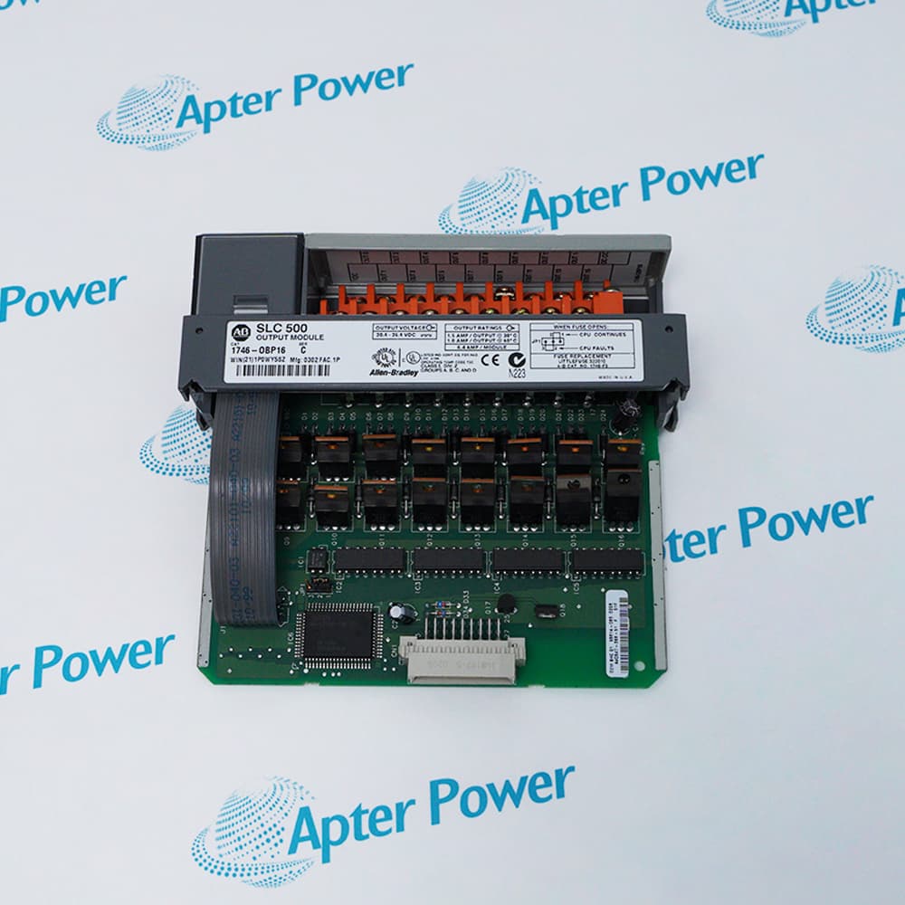
- Operates in conjunction with main modules such as the 1404-M405A-RIO Powermonitor 3000
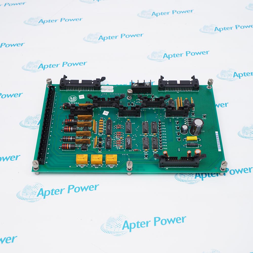
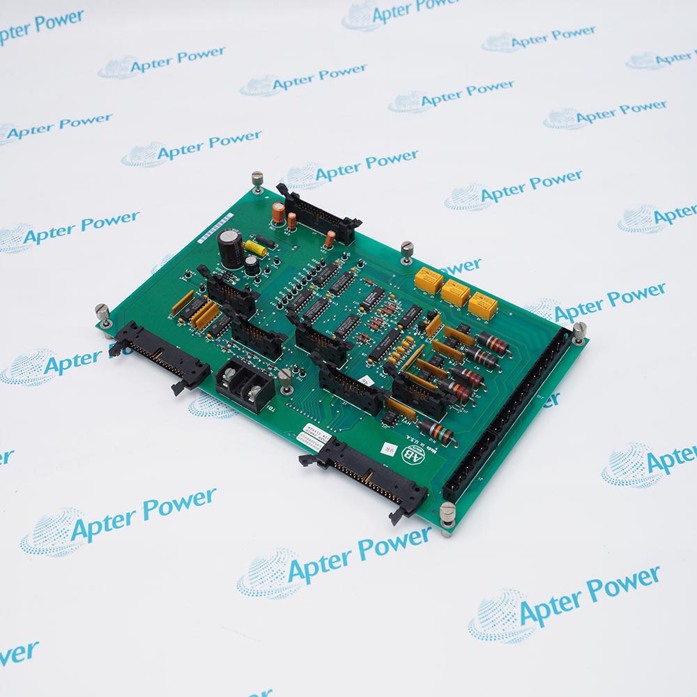
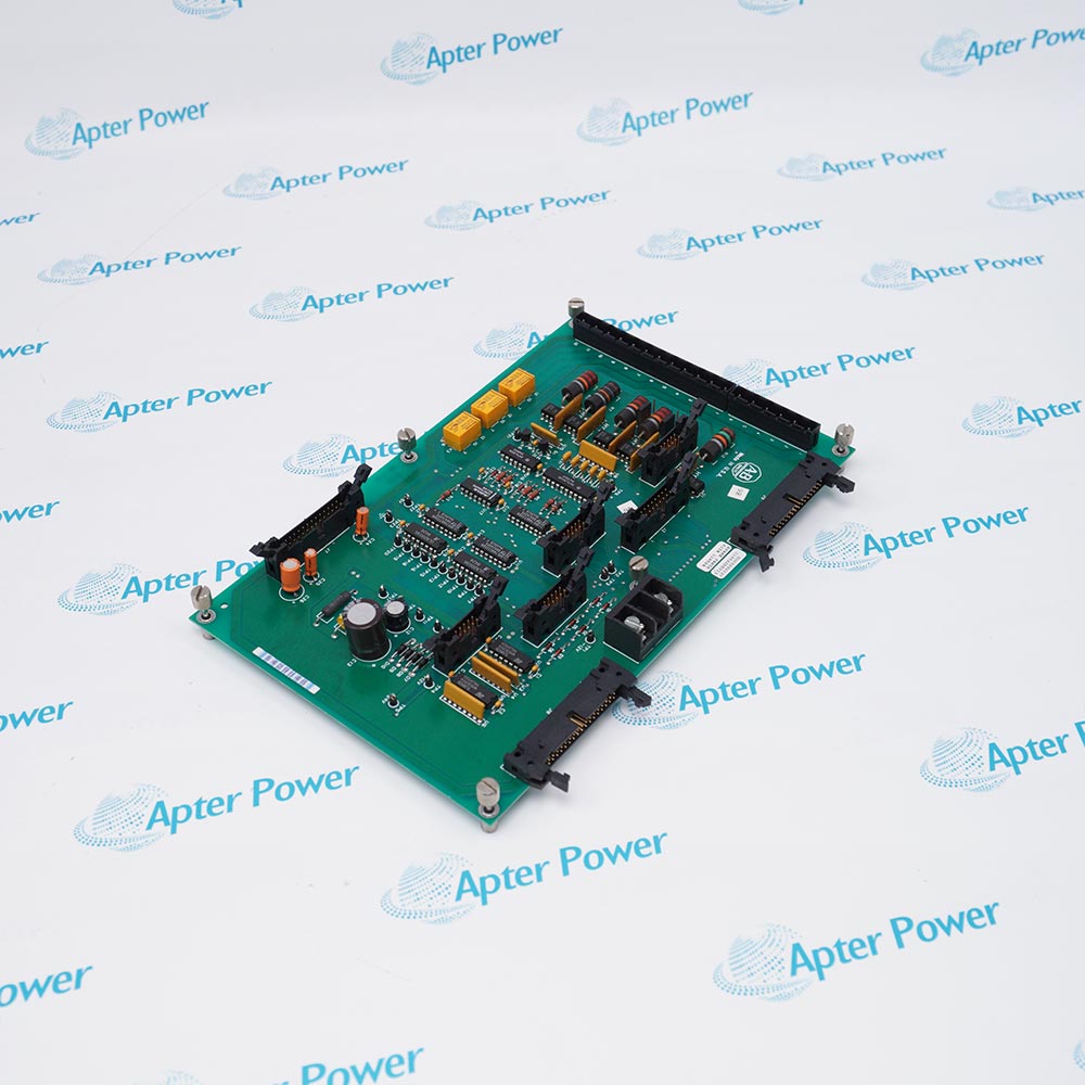
The 119524-129708-01 functions as a dedicated power stage interface board within industrial power monitoring systems, serving as the critical communication interface between the logic control unit and the high-voltage power stage. The module continuously processes signals from the power stage, ensuring accurate acquisition of power data and transmitting this information to the programmable logic controller (PLC) via a Remote I/O (RIO) network. The 119524-129708-01 is specifically engineered to address electrical noise and signal attenuation challenges in heavy-duty industrial environments, effectively solving the problem of unreliable data transmission between high-power circuits and sensitive control electronics, thereby ensuring engineers receive real-time, accurate diagnostic information.
The 119524-129708-01 provides essential power stage interface functions that are critical to the entire monitoring path, directly affecting the proper and normal operation of the overall monitor system. This module is equipped with 8 RS-232 serial communication ports, supporting data transmission rates up to 115.2 kbps. The 119524-129708-01 operates with a power consumption of 5W and features a compact form factor suitable for various installation environments. The operating temperature range of the 119524-129708-01 spans from -40°C to +85°C, enabling adaptation to harsh industrial field conditions.
The 119524-129708-01 is typically identified by its core part numbers 119524-129708-01 and 119522, manufactured in the USA to meet stringent industrial reliability and signal integrity standards. This module operates in conjunction with related 119524 and 119522 components to form a complete power stage interface solution, widely deployed in drive interface applications within industrial automation control systems, including large motor control centers and factory power distribution networks.
The 119524-129708-01 Allen-Bradley Power Stage Interface Board may still be available for purchase and support from Apter Power beyond End-Of-Life (EOL) by the manufacturer (OEM).
Allen-Bradley 119524-129708-01 Power Stage Interface Board Manuals,Datasheets,Link
Important Notice: Other accessories, manuals, cables, calibration data, software, etc. are not included with this equipment unless listed in the above stock item description. All prices are shown in USD.
Allen-Bradley 119524-129708-01 Power Stage Interface Board Specs
General
- Manufacturer Allen-Bradley
- Model 119524-129708-01
- Condition New Original ready stock
- Product Family 1404-DM 119522 129708-01
Important Notice: Other accessories, manuals, cables, calibration data, software, etc. are not included with this equipment unless listed in the above stock item description. All prices are shown in USD.
- Signal Scaling and Feedback: It converts and scales feedback signals from discrete I/O for processing by the Main Control Board.
- SCR Gate Firing: The board manages the gate pulses used to fire armature and field Silicon Controlled Rectifiers (SCRs), which are essential for DC motor speed and torque control.
- Voltage Synchronization: It synchronizes 3-phase AC power signals to ensure precise control of the power stage.
- Safety and Feedback Monitoring: It monitors motor thermal inputs and reset signals, ensuring the drive operates within safe thermal limits.
- Access: The board is typically located behind the first swing-down panel in a Bulletin 1395 enclosure.
- Mounting: Snap the board onto the designated standoffs on the backing plate, ensuring all locking tabs are secure.
- Voltage Configuration: Before connecting power, set Jumpers J11 and J12 to match your input voltage for Reset and Motor Thermo signals (Position 1-2 for 115 VAC, Position 2-3 for 24 VDC).
- Cabling: Reconnect all ribbon cables (J9, J10, J13) and wire connectors (J2 through J14 and TB2).
- Grounding: Ensure the functional and protective earth grounds are properly connected to prevent electrical interference.
- Initialization: Use a programming terminal (like the DMT or ITS) to select EEPROM functions and then Initialize. This forces the Main Control Board to recognize the interface ports and save default values.
- Parameter Loading: After initialization, you must reload application-specific parameter data, either manually or via a saved file from DriveTools.
- Test Points: Use test points TP7 through TP20 on the board to monitor gate pulses. A healthy signal appears as a +24V square wave during SCR firing.