Ask our team:
  • Phone: +86 181 0690 9650
  • E-Mail sales1@apterpower.com

8BVI0028HWD0.000-1

/ 4.9
1001 reviews | Need a Specific Revision?
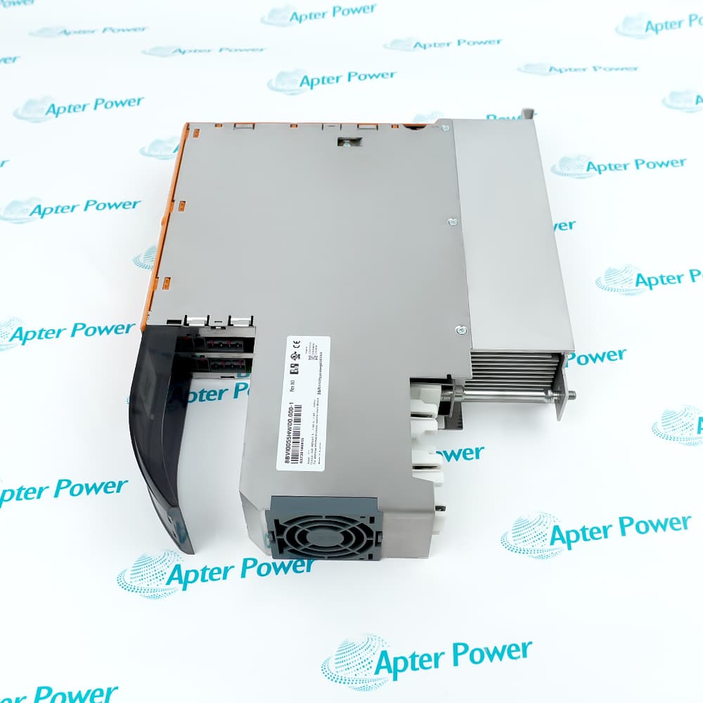
B&R 8BVI0028HWD0.000-1 is an ACOPOSmulti 2-axis inverter module rated 3.8 Aeff continuous per motor connection with wall mounting.
In Stock
Ships by Wednesday, October 28
Fast Shipping Available
Get a quick price for 8BVI0028HWD0.000-1
Quantity
*E-mail
Company
*Mobile
*Content
Upload (gif, jpg, jpeg, png, bmp, doc, docx, xls, xlsx, ppt, pdf, csv)

Technical specifications for 8BVI0028HWD0.000-1

  • Manufacturer:
    B&R
  • Part Number:
    8BVI0028HWD0.000-1
  • Product Family:
    B&R ACOPOS
  • Product Type:
    ACOPOSmulti 2-axis Inverter Module
  • Stock:
    1
  • Motor connections:
    2
  • Continuous power per motor connection:
    2.8 kW
  • Continuous current per motor connection:
    3.8 Aeff
  • Peak current per motor connection:
    9.5 Aeff
  • Nominal DC bus voltage:
    750 VDC
  • Continuous DC bus power consumption:
    5.73 kW
  • DC bus capacitance:
    165 µF
  • 24 VDC supply input:
    25 VDC ±1.6%
  • Slots for plug-in modules:
    2
  • Nominal switching frequency:
    5 kHz
  • Maximum output frequency:
    598 Hz
  • Dynamic node allocation:
    Supported
  • Degree of protection:
    IP20
  • Operating temperature:
    5 to 40 °C nominal; 55 °C maximum with derating
  • Maximum installation elevation:
    4000 m; current derating starts above 500 m
  • Dimensions:
    5.3 × 31.7 × 26.3 cm
  • Weight:
    2.8 kg
  • Tariff Code:
    8503009090
  • Country of origin:
    Germany
  • Place of shipment:
    Xiamen, Fujian, China
By purchasing this item, you agree to the Terms & Conditions, ApterPower is not an authorized distributor for listed manufacturers or tradenames and therefore the manufacturer's warranty does not apply. All our products come with ApterPower's 1-year warranty.

More Information

Overview Manuals DC Bus Axis Configuration Installation Application
  • Provides 2 independent motor connections at 3.8 Aeff each
  • Installs by wall mounting on an ACOPOSmulti system
  • Includes motor-brake, temperature-sensor, enable and trigger interfaces

8BVI0028HWD0.000-1 is an ACOPOSmulti 2-axis inverter module rated 3.8 Aeff continuous per motor connection with wall mounting.

It supplies 2 independently controlled motor axes from the ACOPOSmulti DC bus and provides motor-brake, temperature-sensor, enable and trigger connections.

Before installation or replacement, verify the complete material number and ACOPOSmulti backplane and power-supply compatibility, cooling method, motor and feedback data, required terminal and shielding sets, plug-in modules, saved parameters, enable wiring, grounding and cabinet thermal design.

Availability, condition, price, and shipping time for 8BVI0028HWD0.000-1 are confirmed during quotation.

B&R 8BVI0028HWD0.000-1 Manuals, Datasheets, Links

Important Notice: Other accessories, manuals, cables, calibration data, software, etc. are not included with this equipment unless listed in the above stock item description. All prices are shown in USD.

  • The inverter operates from the ACOPOSmulti 750 VDC nominal bus
  • The 25 VDC electronics supply and bus power must both be available
  • Backplane, supply and regenerative power budgets must be checked for the full station
  • The module provides 2 motor connections
  • Each connection is rated 3.8 Aeff continuous and 9.5 Aeff peak
  • Motor, feedback, brake and temperature-sensor assignments must match the saved project
  • The documented mounting method is wall mounting
  • Airflow or cold-plate thermal design must satisfy the documented derating limits
  • Required terminal, shielding and plug-in components must be confirmed separately
  • Woodworking machinery using synchronized feeder and cutting axes
  • Material-handling equipment requiring coordinated conveyor and indexing motion
  • Metalworking machines using auxiliary positioning and transfer axes
Description
8BVI0028HWD0.000-1 is an ACOPOSmulti 2-axis inverter module rated 3.8 Aeff continuous per motor connection with wall mounting.

It supplies 2 independently controlled motor axes from the ACOPOSmulti DC bus and provides motor-brake, temperature-sensor, enable and trigger connections.

Before installation or replacement, confirm the complete material number and ACOPOSmulti backplane and power-supply compatibility, cooling method, motor and feedback data, required terminal and shielding sets, plug-in modules, saved parameters, enable wiring, grounding and cabinet thermal design.
Alternative Names
8BVI0028HWD0.000-1 8BVI0028HWD0 000 1 8BVI0028HWD00001 B&R 8BVI0028HWD0.000-1 BR 8BVI0028HWD0.000-1 B&R ACOPOSmulti 8BVI0028HWD0.000-1 ACOPOSmulti 8BVI0028HWD0.000-1
Technical notes
B&R 8BVI0028HWD0.000-1 requires exact motor, feedback, power, cooling, accessory and parameter matching. Record the installed configuration and validate grounding, shielding, thermal limits, enable or safety wiring and controlled startup before returning the axis to service.
Exceptional Service

Our Mission

  • 100% Satisfaction

    We believe expertise is priceless. With over 20 years of experience, and top engineers on staff, we can help you solve or avoid problems that threaten your business.
  • Trust Guaranteed

    Not only do we have a vast inventory, our team makes sure every piece of equipment is in working condition. Your purchases are also backed by our Warranty.
  • Expertise

    Time is money, especially when your equipment is down. We work quickly to get your equipment on its way so you can get it back up and running.

FAQS

The following is a list of questions commonly asked by our customers. Please contact us if you have a question about our process that is not answered below.
Why must the motor cable length be checked when installing B&R 8BVI0028HWD0.000-1?
Excessive motor-cable length can increase capacitive current, electrical stress and EMC problems. Keep the cable within 25 m at 5 or 10 kHz and within 10 m at 20 kHz, and use the specified shielded motor-cable arrangement.
What should be verified before reusing the existing feedback hardware with B&R 8BVI0028HWD0.000-1?
Confirm feedback technology, plug-in module catalog number, firmware support, connector keying, cable pinout and length, shielding, encoder supply, and the physical condition of every connector.
How are the auxiliary 24 VDC outputs protected on B&R 8BVI0028HWD0.000-1?
The two auxiliary outputs use 250 mA slow-blow electronic protection with automatic reset.
What network and project information should be recorded for B&R 8BVI0028HWD0.000-1?
Record the controller project version, hardware-tree position, node and axis names, firmware, bus configuration, safety mapping, machine options, and the approved backup file used for restoration.
How does installation elevation affect B&R 8BVI0028HWD0.000-1?
Above 500 m, B&R specifies continuous-current derating of 0.38 Aeff per additional 1000 m. The documented maximum installation elevation is 4000 m.
How should production testing be staged after installing B&R 8BVI0028HWD0.000-1?
Start with wiring and insulation checks, confirm project recognition and feedback, test each brake and axis separately at low speed, validate limits and safety, then progress to synchronized cycles and full-load temperature monitoring.
What should be checked after installing B&R 8BVI0028HWD0.000-1?
Confirm connectors and shielding, cooling, bus and 24 VDC voltages, project hardware identity, feedback direction, motor brake, enable chain, fault-free startup and controlled low-speed motion before production.