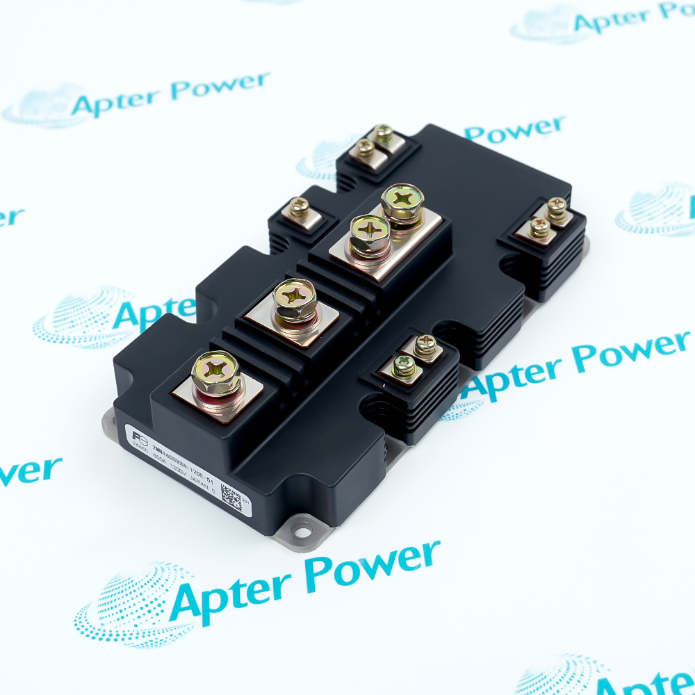
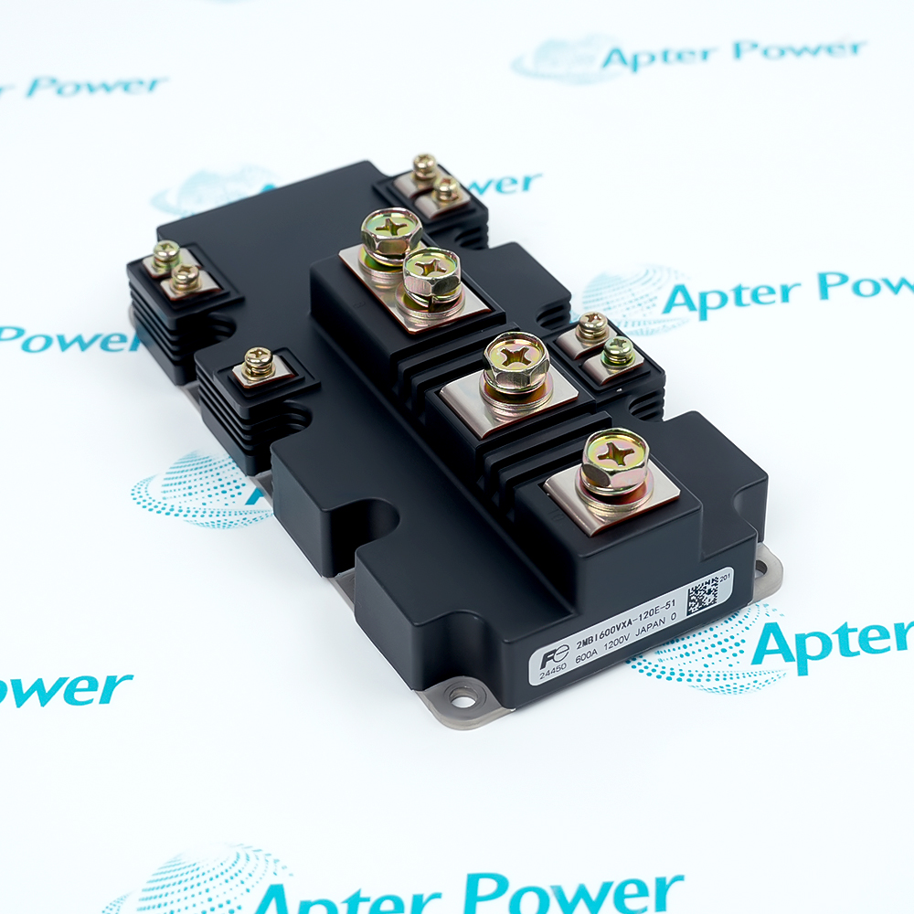
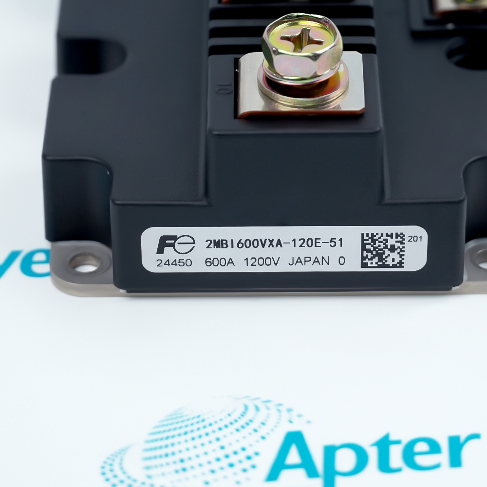
Features:
- Uses a 1200 V, 600 A two-pack IGBT arrangement for one high-power inverter half-bridge.
- Combines sixth-generation V-Series chips with an M271 PrimePACK low-inductance current path.
- Routes heat through the insulated module base while screw terminals carry the main power connections.
Fuji Electric 2MBI600VXA-120E-51 places two controlled IGBT and freewheel-diode paths in one power module.
The gate driver controls the two switch positions while the anti-parallel diodes carry reverse current during load commutation.
The complete -51 suffix, electrical ratings, terminal arrangement, gate-drive conditions, and cooling interface must be matched together.
The Fuji Electric 2MBI600VXA-120E-51 1200 V 600 A 2-Pack IGBT Module may still be available for purchase and support from Apter Power beyond End-Of-Life (EOL) by the manufacturer (OEM).
Fuji Electric 2MBI600VXA-120E-51 1200 V 600 A 2-Pack IGBT Module Manuals,Datasheets,Link
Important Notice: Other accessories, manuals, cables, calibration data, software, etc. are not included with this equipment unless listed in the above stock item description. All prices are shown in USD.
Two-switch current flow
- Upper device: One IGBT controls the upper current path of the inverter half-bridge.
- Lower device: The second IGBT switches the complementary path from the output node.
- Freewheel paths: Anti-parallel diodes carry inductive current when an IGBT turns off.
- Gate control: Separate drive commands determine when each semiconductor path conducts.
Voltage and gate boundaries
- Voltage class: The module is identified for a 1200 V collector-emitter rating.
- Current class: The product label identifies the 600 A module rating.
- Gate limit: Gate-emitter voltage must stay inside the documented ±20 V boundary.
- Switching values: Drive resistance and operating conditions determine actual switching time and loss.
Junction-to-heatsink path
- Junction limit: Semiconductor junction temperature must remain below the documented maximum.
- Module base: Heat passes through the insulated baseplate into the mounting surface.
- Interface: Flatness, clamping force, and thermal-interface material affect heat transfer.
- Monitoring: Temperature feedback supports protection but does not replace junction-loss calculations.
Full-suffix replacement checks
- Part marking: Match the complete 2MBI600VXA-120E-51 identifier rather than the base family alone.
- Package: Confirm the M271 PrimePACK outline and screw-terminal positions against the installed module.
- Driver: Verify gate voltage, resistance, isolation, and protection settings before energizing the replacement.
- Cooling: Recheck heatsink condition, mounting pressure, and thermal interface during installation.