Ask our team:
  • Phone: +86 181 0690 9650
  • E-Mail sales1@apterpower.com
  • Lifecycle status

    Discontinued / Obsolete by OEM
    Apter Power can quote DS200FCGDH1A, provide the relevant General Electric manual, and assist with checking an officially documented catalog identity for replacement inquiries.

DS200FCGDH1A

/ 4.9
1001 reviews | Need a Specific Revision?
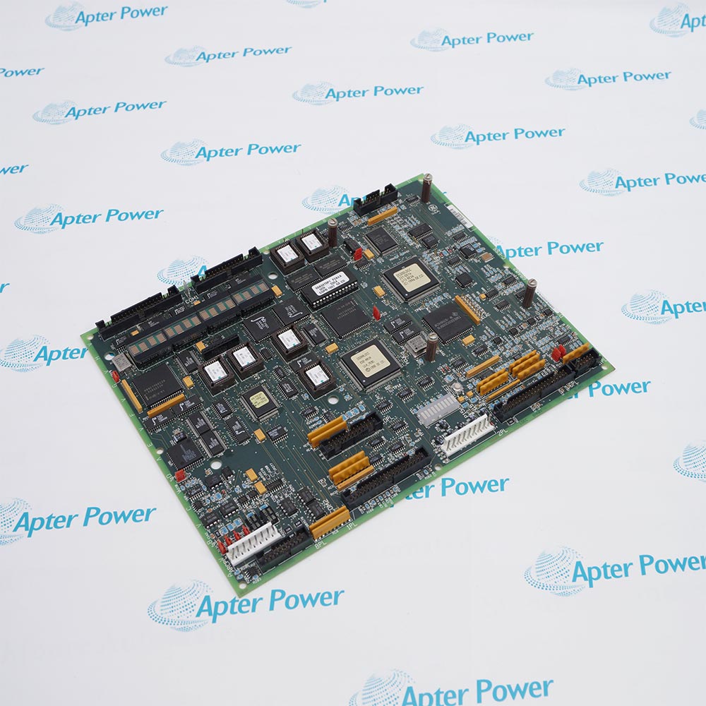
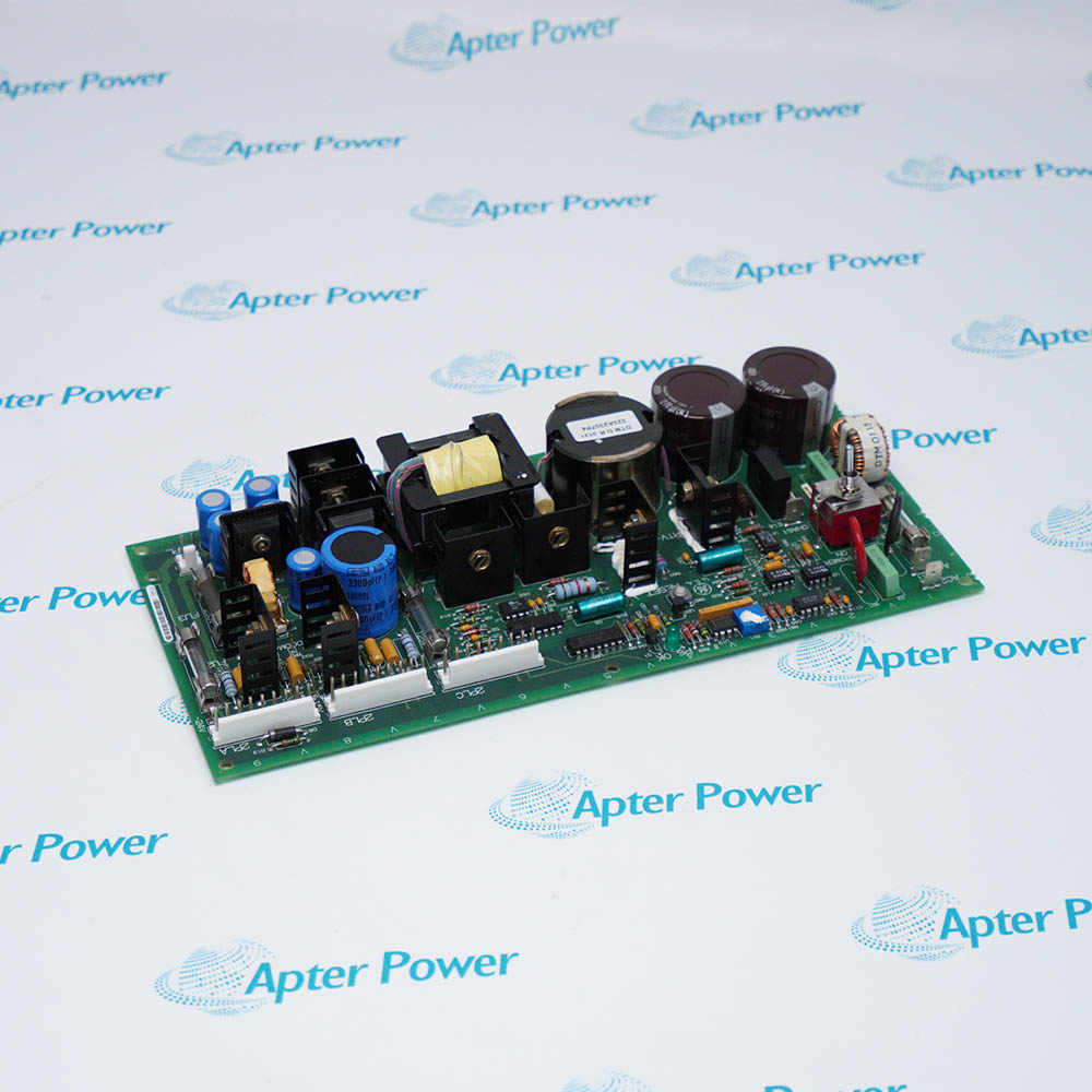
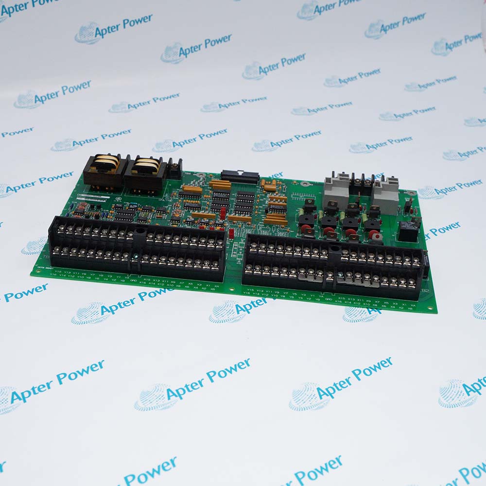
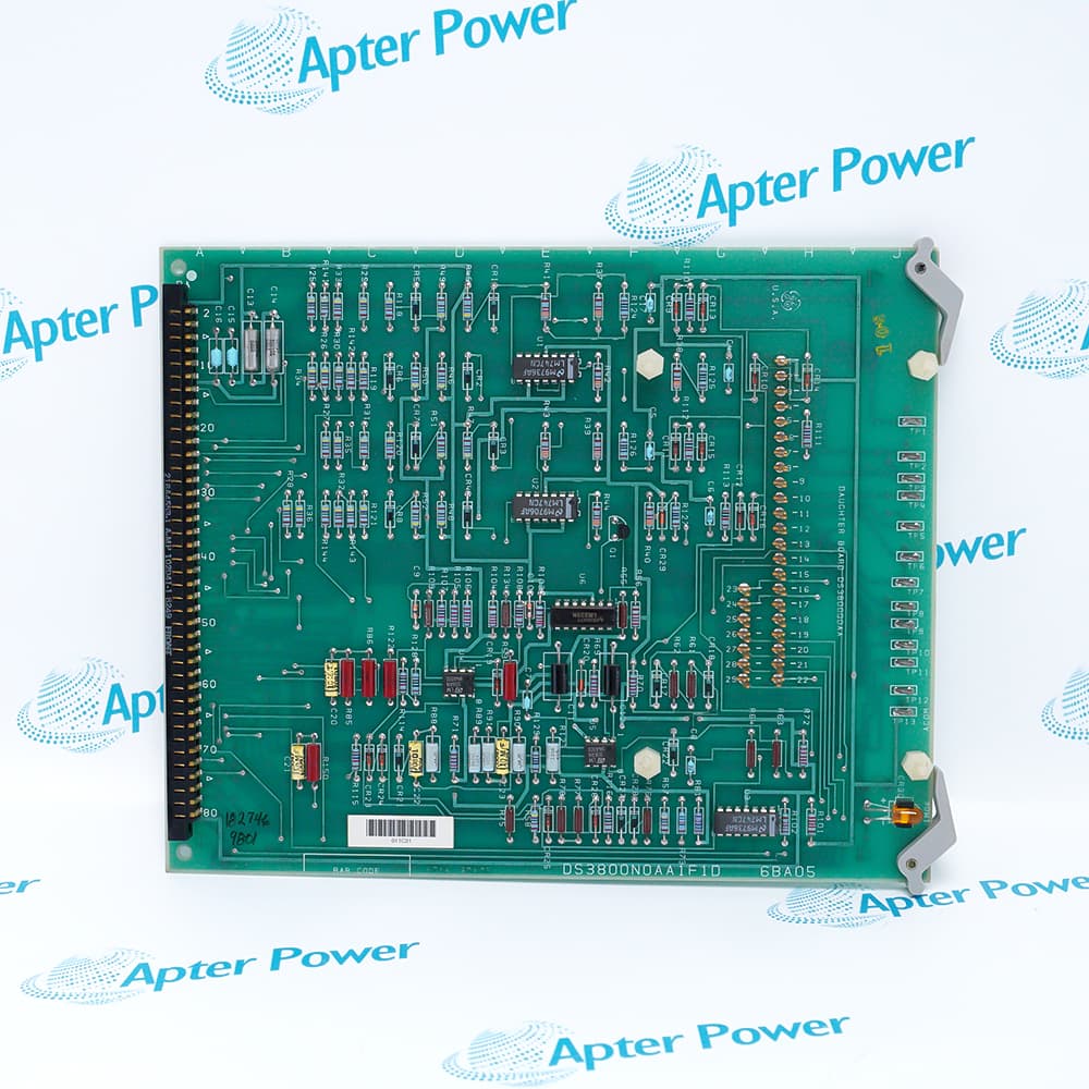
General Electric DS200FCGDH1A is a Gate Distribution and Status Board that distributes six bridge-leg firing commands and returns cell, voltage, current, and diagnostic feedback to the VME host.
In Stock
Ships by Wednesday, October 28
Fast Shipping Available
Get a quick price for DS200FCGDH1A
Quantity
*E-mail
Company
*Mobile
*Content
Upload (gif, jpg, jpeg, png, bmp, doc, docx, xls, xlsx, ppt, pdf, csv)

Technical specifications for DS200FCGDH1A

  • Manufacturer:
    General Electric
  • Part Number:
    DS200FCGDH1A
  • Product Family:
    GE Mark V/VI Driver Board
  • Product Type:
    Gate Distribution and Status Board
  • Stock:
    1
  • Bridge configuration:
    6-pulse phase-controlled non-reversing bridge
  • VME interface:
    A24/D16
  • Firing outputs:
    Six fiber-optic transmitters, LEG1 through LEG6
  • Cell-status inputs:
    Three fiber-optic receivers, STAT1 through STAT3
  • System clock:
    16-bit up-counter with rollover at 0FFFFH
  • Heartbeat limit:
    Approximately 8 ms before gating and IMOK turn off
  • Feedback conversion:
    Eight VCO accumulators and six parallel sigma-delta converters
  • Hardware overcurrent filter:
    Approximately 26 ms
  • Tariff Code:
    8504909000
  • Country of origin:
    USA
  • Place of shipment:
    Xiamen, Fujian, China
By purchasing this item, you agree to the Terms & Conditions, ApterPower is not an authorized distributor for listed manufacturers or tradenames and therefore the manufacturer's warranty does not apply. All our products come with ApterPower's 1-year warranty.

More Information

Overview Manuals Firing & Fiber Feedback Paths Protection Logic Rack & Diagnostics

Features:

  • A six-entry firing mask controls six fiber-optic outputs for the individual bridge legs.
  • Three fiber-optic status inputs combine leg-cell and power-supply returns into a 16-bit status word.
  • VCO, Sigma-Delta, zero-crossing, heartbeat, and hardware-overcurrent circuits return timed bridge feedback and protection status to the VME host.
The 16-bit system clock timestamps three zero-crossing latches and the accumulated analog-feedback values before the host reads them over VME.

P2 assigns the board address automatically when the board changes rack position, but the front-panel OC_SP level still requires manual adjustment for the connected source-side CT or load-side LEM scaling.

Host-commanded loopback and analog-signal injection support board selftests, while IMOK and OC FLT provide separate visual indications for heartbeat operation and latched overcurrent.

The General Electric DS200FCGDH1A Gate Distribution and Status Board may still be available for purchase and support from Apter Power beyond End-Of-Life (EOL) by the manufacturer (OEM).
General Electric DS200FCGDH1A Gate Distribution and Status Board Manuals,Datasheets,Link Important Notice: Other accessories, manuals, cables, calibration data, software, etc. are not included with this equipment unless listed in the above stock item description. All prices are shown in USD.

Following commands through the optical paths

  • Firing mask: Six register entries correspond to the six cell strings in the bridge.
  • Transmitters: LEG1 through LEG6 can send as many as six simultaneous fiber-optic firing signals.
  • Status receivers: STAT1, STAT2, and STAT3 accept multiplexed returns from three FGPA boards.
  • Status word: Two sets of leg-cell states and the power-supply states are stored as one 16-bit value.

Separating bridge measurement channels

  • Voltage path: A 20-pin NATO cable supplies scaled DC and three phase-voltage signals within a ±10 V electronics range.
  • Current path: Source-side CTs or load-side LEM modules supply IA and IC, with IB derived by the conditioning circuits.
  • Frequency conversion: Eight VCO inputs accumulate in separate 16-bit counters before a host read command transfers the values.
  • Parallel conversion: Six Sigma-Delta channels digitize voltage and current signals alongside the VCO paths.

Tracing inhibited or latched gating

  • CTLN1 loop: Absence of the 24 V DC hardware loop blocks cell gating independently of the host CPU.
  • Heartbeat: An interval beyond approximately 8 ms turns off IMOK and gating until a hard reset.
  • Overcurrent: IFB above the front-panel OC_SP level for approximately 26 ms latches the hardware overcurrent signal.
  • Commutation check: Leg current outside the firing interval and overlap window increments a counter for the affected bridge leg.

Confirming rack assignment and board state

  • P1 interface: The 96-pin connector carries the A24/D16 VME bus.
  • P2 assignment: Backplane pins set the VME address automatically and carry inter-board I/O signals.
  • Front indicators: IMOK green reports an active heartbeat; OC FLT red reports latched overcurrent protection.
  • Selftest: Host commands exercise loopback functions and inject test signals into analog paths.
Description
General Electric DS200FCGDH1A is a Gate Distribution and Status Board for a six-pulse phase-controlled non-reversing bridge. It receives SCR firing information from the DS200DSPC processor and returns bridge feedback and diagnostic data through the VME backplane.

On DS200FCGDH1A, a firing mask controls six optical gate-command transmitters, while status returns from three FGPA boards are combined into the cell-status data sent back to the processor. The board also time-stamps feedback events using its local system clock.

Voltage signals arriving from the NATO scaling board and current feedback from bridge sensors are conditioned for the control system by DS200FCGDH1A. Its hardware overcurrent circuit, heartbeat supervision, IMOK indicator, and self-test paths give separate evidence of gating readiness and board health.
Alternative Names
GE DS200FCGDH1A General Electric DS200FCGDH1A DS200-FCGD-H1A DS200 FCGD H1A FCGD DS200FCGDH1A DS200FCGD H1A LS2100 DS200FCGDH1A DS200FCGDH1A Gate Distribution and Status Board
Technical notes
DS200FCGDH1A has no fuses or other end-user-serviceable parts. Isolate and verify drive power, handle the board as static-sensitive, and disconnect each fiber-optic cable by its latched connector rather than pulling the fiber.
Exceptional Service

Our Mission

  • 100% Satisfaction

    We believe expertise is priceless. With over 20 years of experience, and top engineers on staff, we can help you solve or avoid problems that threaten your business.
  • Trust Guaranteed

    Not only do we have a vast inventory, our team makes sure every piece of equipment is in working condition. Your purchases are also backed by our Warranty.
  • Expertise

    Time is money, especially when your equipment is down. We work quickly to get your equipment on its way so you can get it back up and running.

FAQS

The following is a list of questions commonly asked by our customers. Please contact us if you have a question about our process that is not answered below.
Why can DS200FCGDH1A stop gating while the VME host still has power?
On DS200FCGDH1A, a missing 24 V DC CTLN1 loop or an expired heartbeat removes gating independently of host power; check CTLN1 and IMOK before replacing hardware.
If one bridge leg receives no firing pulse from DS200FCGDH1A, where should tracing begin?
Trace the affected DS200FCGDH1A LEG1–LEG6 fiber, verify its latch and fiber condition, then compare the firing mask with the matching FGPA cell-status return.
What must be rechecked after DS200FCGDH1A is moved to another rack position?
A relocated DS200FCGDH1A discovers its VME address through P2, but OC_SP must still match the source-side CT or load-side LEM scaling at the new position.
How can a latched OC FLT on DS200FCGDH1A be cleared safely?
Reset DS200FCGDH1A only after the sustained overcurrent cause has been removed, because the hardware detector keeps OC FLT latched after current falls.
Which DS200FCGDH1A checks separate a voltage-feedback loss from a current-feedback loss?
Compare the DS200FCGDH1A VDC and AC voltage paths through the NATO ribbon cable with the IA and IC testpoints from the bridge sensors.
When the commutation-failure count on DS200FCGDH1A keeps rising, what does it indicate?
Repeated increments on DS200FCGDH1A show that leg current remains outside the commanded gating interval and permitted overlap, pointing to a recurring current or timing mismatch.
Can a passing DS200FCGDH1A self-test prove that the external bridge paths are healthy?
Passing a DS200FCGDH1A loopback or analog-injection test checks onboard functions only; fibers, CTLN1 wiring, and bridge sensors still require separate verification.

Product Browsing History