Ask our team:
  • Phone: +86 181 0690 9650
  • E-Mail sales1@apterpower.com
  • Lifecycle status

    Discontinued / Obsolete by OEM
    Quotation support and the relevant GE technical file for DS200TCTGG1A are available from Apter Power for order review.

DS200TCTGG1A

/ 4.9
1001 reviews | Need a Specific Revision?
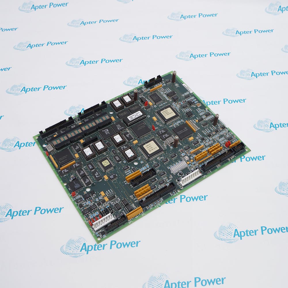
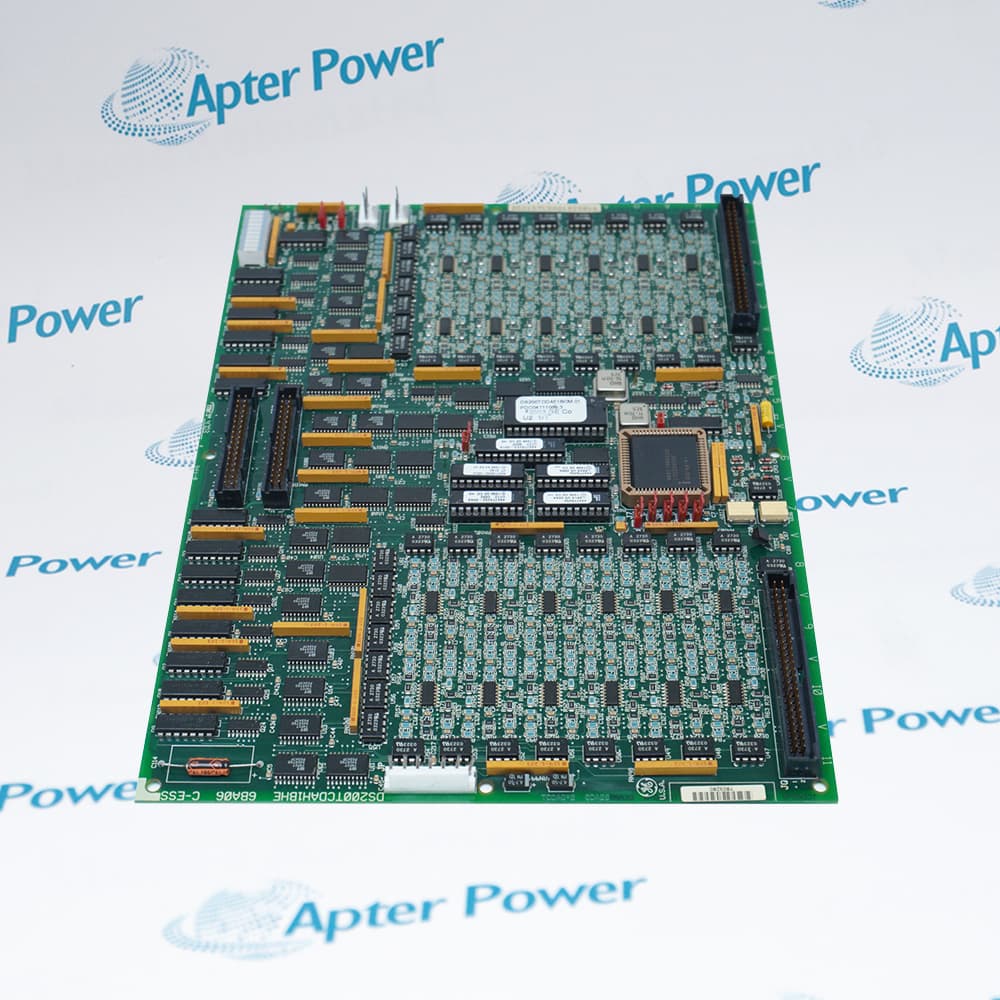
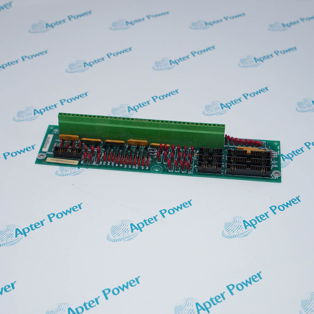
General Electric DS200TCTGG1A is the Mark V LM turbine trip board in the P1 core, combining primary and emergency trip relay paths for failsafe fuel-shutoff valve operation.
In Stock
Ships by Thursday, October 29
Fast Shipping Available
Get a quick price for DS200TCTGG1A
Quantity
*E-mail
Company
*Mobile
*Content
Upload (gif, jpg, jpeg, png, bmp, doc, docx, xls, xlsx, ppt, pdf, csv)

Technical specifications for DS200TCTGG1A

  • Manufacturer:
    General Electric
  • Part Number:
    DS200TCTGG1A
  • Product Family:
    GE Mark V/VI Driver Board
  • Product Type:
    Turbine Trip Board
  • Stock:
    1
  • Board Type:
    Turbine trip board
  • Core Position:
    Location 4 in P1
  • Trip Architecture:
    Primary PTR and emergency ETR relays
  • Emergency Voting:
    Two-out-of-three through TCEA X/Y/Z
  • Protective Bus:
    24 V dc to PTR and ETR relay circuits
  • Board Power Feed:
    125 V dc from TCPD through J7W
  • Synchronizing Function:
    Voted automatic synchronizing plus independent synch-check permissive
  • Board Configuration:
    J1 hardware jumper; no software configuration
  • Tariff Code:
    8537109090
  • Country of origin:
    USA
  • Place of shipment:
    Xiamen,Fujian,China
By purchasing this item, you agree to the Terms & Conditions, ApterPower is not an authorized distributor for listed manufacturers or tradenames and therefore the manufacturer's warranty does not apply. All our products come with ApterPower's 1-year warranty.

More Information

Overview Manuals Trip Relays Voting Paths Connectors Trip Verification

Features:

  • Combines primary and emergency trip relay paths in the Mark V LM P1 protective core.
  • Implements a three-leg TCEA input arrangement for two-out-of-three emergency voting.
  • Includes synchronizing relays alongside breaker, trip, and alarm-horn signal interfaces.
Primary and emergency trip commands reach separate relay groups, allowing the control-sequence path and the independent protective path to be evaluated individually.

The hardwired trip circuit de-energizes both relay groups by removing their 24 V DC supply, so the protective action does not depend on one software command.

Generator and bus signals share the JDR, JDS, and JDT chain with synchronizing commands, giving the board a second role beyond fuel-shutoff valve tripping.

For General Electric DS200TCTGG1A Turbine Trip Board, Apter Power provides quotation and document assistance after the manufacturer's end-of-life stage.
General Electric DS200TCTGG1A Turbine Trip Board Manuals, Datasheets, Links Important Notice: Other accessories, manuals, cables, calibration data, software, etc. are not included with this equipment unless listed in the above stock item description. All prices are shown in USD.

DS200TCTGG1A Relay Operating Paths

  • Primary source: PTR operation follows communication-fault and control-sequence commands received from TCQA.
  • Emergency source: ETR operation is driven independently by the X, Y, and Z TCEA boards.
  • Hardwired action: Removing the shared 24 V DC supply de-energizes both PTR and ETR groups into the trip state.
  • Output purpose: The relay contacts operate the turbine fuel-shutoff valve circuits assigned to the P1 core.

Three-Leg Emergency Voting

  • X leg: JLX carries the X-channel TCEA input to emergency relays K5 and K8.
  • Y leg: JLY brings the Y-channel command to relays K4 and K7 on DS200TCTGG1A.
  • Z leg: JLZ delivers the third protective input to relays K6 and K9.
  • Vote result: Two agreeing TCEA legs are sufficient to operate the emergency trip path.

DS200TCTGG1A Interface Groups

  • J7W supply: Receives 125 V DC from the TCPD power-distribution path.
  • JLX-JLZ group: Carries the three emergency-trip commands and the protective 24 V DC connection.
  • JDR-JDT chain: Transfers primary-trip, synchronizing, generator, and bus signals through the board.
  • JN and JM: Exchange breaker-close, trip, and alarm-horn signals with PTBA; JT is normally unused.

Proving DS200TCTGG1A Protective Action

  • PTR response: Compare each control-sequence trip command with the corresponding primary relay state.
  • Leg response: Exercise the X, Y, and Z emergency inputs separately and identify the matching JLX, JLY, or JLZ path.
  • Voting response: Confirm that the emergency output follows the intended two-out-of-three logic rather than one isolated leg.
  • Synchronizing check: Verify that generator and bus inputs reach the onboard synchronizing relays through the daisy-chained connector group.
Description
Installed at location four in the Mark V LM P1 protective core, General Electric DS200TCTGG1A is the TCTG turbine trip board that operates fuel-shutoff valves through primary and emergency relay paths.

The primary trip relays on DS200TCTGG1A respond to communication-fault and control-sequence logic. Emergency trip relays receive three separate TCEA inputs through JLX, JLY, and JLZ, creating the two-out-of-three voting path used for an emergency trip.

Hardwired trip pushbuttons remove the 24 V DC supply from both PTR and ETR relay groups, while J7W brings 125 V DC from TCPD. Through JN and JM, DS200TCTGG1A exchanges breaker-close, hardwired-trip, emergency-trip, and alarm-horn signals with PTBA.

JDR, JDS, and JDT form a daisy-chained control path on DS200TCTGG1A. Those connectors carry primary-trip and synchronizing commands from TCQA together with generator and bus signals used by the synchronizing relays located on the board.
Alternative Names
DS200-TCTG-G1A DS200 TCTG G1A GE DS200TCTGG1A General Electric DS200TCTGG1A GE Mark V DS200TCTGG1A DS200TCTG G1A TCTG DS200TCTGG1A DS200TCTGG1A Turbine Trip Board
Technical notes
DS200TCTGG1A is part of the turbine trip chain; record J7W, JDR/JDS/JDT, JLX/JLY/JLZ, JN, and JM connections before any change.
Exceptional Service

Our Mission

  • 100% Satisfaction

    We believe expertise is priceless. With over 20 years of experience, and top engineers on staff, we can help you solve or avoid problems that threaten your business.
  • Trust Guaranteed

    Not only do we have a vast inventory, our team makes sure every piece of equipment is in working condition. Your purchases are also backed by our Warranty.
  • Expertise

    Time is money, especially when your equipment is down. We work quickly to get your equipment on its way so you can get it back up and running.

FAQS

The following is a list of questions commonly asked by our customers. Please contact us if you have a question about our process that is not answered below.
Why does a hardwired trip pushbutton act on both DS200TCTGG1A trip paths?
The hardwired input removes the 24 V dc supply to both PTR and ETR relays on DS200TCTGG1A, forcing the failsafe trip independently of a single command path.
What should be checked when one DS200TCTGG1A emergency-vote leg is missing?
Trace the affected DS200TCTGG1A JLX, JLY, or JLZ connection to its X, Y, or Z TCEA board and verify the corresponding ETR relay and 24 V protective bus.
Why can DS200TCTGG1A synchronizing signals be affected together?
DS200TCTGG1A daisy-chains JDR, JDS, and JDT, which carry synchronizing commands and generator/bus signals in addition to PTR trip commands.
What does loss of the DS200TCTGG1A J7W feed indicate?
J7W carries 125 V DC from TCPD to DS200TCTGG1A, so loss at that connector affects the board power path rather than one isolated trip input.
Which DS200TCTGG1A connectors should be checked for breaker-close or alarm-horn issues?
DS200TCTGG1A exchanges breaker-close, hardwired-trip, emergency-trip, and alarm-horn signals with PTBA through JN and JM.
How can the DS200TCTGG1A PTR and ETR paths be separated during diagnosis?
For DS200TCTGG1A, compare the TCQA-derived PTR commands on JDR/JDS/JDT with the TCEA-derived ETR commands on JLX/JLY/JLZ while confirming the common hardwired-trip supply condition.
What must be demonstrated after DS200TCTGG1A wiring work?
Verify DS200TCTGG1A primary-trip operation, each of the three emergency inputs, the two-out-of-three vote, hardwired-trip de-energization, and the assigned synchronizing signals.