Ask our team:
  • Phone: +86 181 0690 9650
  • E-Mail sales1@apterpower.com
  • Lifecycle status

    Active / Available from OEM
    Apter Power supports DS200FCGDH1B identification review, quotation coordination and sourcing enquiries.

DS200FCGDH1B

/ 4.9
1001 reviews | Need a Specific Revision?
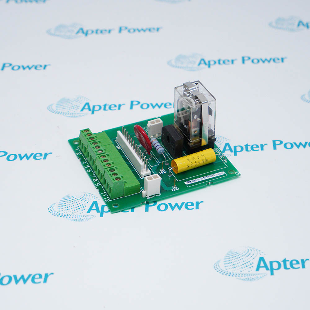
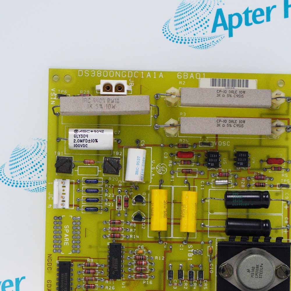
General Electric DS200FCGDH1B is a Gate Distribution and Status Board that timestamps zero crossings, accumulates eight feedback channels, and reports bridge protection status while coordinating six firing paths.
In Stock
Ships by Thursday, October 29
Fast Shipping Available
Get a quick price for DS200FCGDH1B
Quantity
*E-mail
Company
*Mobile
*Content
Upload (gif, jpg, jpeg, png, bmp, doc, docx, xls, xlsx, ppt, pdf, csv)

Technical specifications for DS200FCGDH1B

  • Manufacturer:
    General Electric
  • Part Number:
    DS200FCGDH1B
  • Product Family:
    GE Mark V/VI Driver Board
  • Product Type:
    Gate Distribution and Status Board
  • Stock:
    1
  • VME connectors:
    P1 and P2, 96-pin board-edge connectors
  • Optical firing outputs:
    Six transmitters for bridge legs 1 through 6
  • Optical status inputs:
    Three receivers from FGPA status links
  • Feedback timing:
    Three zero-crossing registers and eight VCO accumulators
  • Analog conversion:
    Six parallel sigma-delta converters
  • Gating inhibit:
    24 V DC CTLN1 hardware loop
  • VME address assignment:
    Automatic from P2 connector data
  • Tariff Code:
    8504909000
  • Country of origin:
    USA
  • Place of shipment:
    Xiamen, Fujian, China
By purchasing this item, you agree to the Terms & Conditions, ApterPower is not an authorized distributor for listed manufacturers or tradenames and therefore the manufacturer's warranty does not apply. All our products come with ApterPower's 1-year warranty.

More Information

Overview Manuals Event Timing Signal Conversion Protection States Product Applications

Features:

  • Three edge-latched zero-crossing channels preserve a 16-bit timer value for bridge-event timing.
  • Eight VCO accumulators and six parallel Sigma-Delta channels provide two conversion paths for conditioned voltage and current feedback.
  • Per-leg commutation counters, reconstructed-flux signals, and software ground-fault and difference-current functions add diagnostic context to the firing data.
A host read command transfers the eight VCO counts together with the system-clock value held in the feedback-time register, allowing measurement data to be related to one acquisition instant.

Front testpoints separate combined current, overcurrent setpoint, phase current, bridge voltage, reconstructed flux, and selected firing outputs without using the factory-only TSTP connectors.

The P2 backplane sets the VME address automatically for the occupied slot and carries the expansion signals shared with the other FCGD boards.

Apter Power supports official-document review, quotation coordination and sourcing enquiries for the General Electric DS200FCGDH1B Gate Distribution and Status Board.
General Electric DS200FCGDH1B Gate Distribution and Status Board Manuals,Datasheets,Link Important Notice: Other accessories, manuals, cables, calibration data, software, etc. are not included with this equipment unless listed in the above stock item description. All prices are shown in USD.
  • System counter: A 16-bit up-counter rolls from 0FFFFH to zero.
  • Zero-crossing latches: Three hardware inputs capture the current counter value at each signal edge.
  • Feedback timestamp: A host command stores the system-clock value with the eight VCO accumulator readings.
  • Commutation window: Each bridge leg is checked against its commanded firing interval plus permitted overlap time.
  • VCO inputs: VA, VB, VC, VDC, IA, IC, FLUXBAR, and FLUXCBR drive eight frequency-conversion channels.
  • VCO registers: Each channel accumulates in a 16-bit counter before the host transfers the set.
  • Sigma-Delta path: Six converters process conditioned voltage and current in parallel with the VCO channels.
  • Flux reconstruction: FBAR, FCBR, and FACR are generated in hardware for timing and diagnostic use.
  • Hardware overcurrent: IFB above OC_SP for approximately 26 ms produces a latched signal cleared only by hardware reset.
  • Commutation failure: Off-window leg current increments a per-leg counter that resets with each new firing mask.
  • Ground fault: Detection is implemented in software using acquired board signals.
  • Difference current: Source-to-source or load-to-source comparison is also implemented in software.
  • LS2100 static-starter control racks using the FCGD as the bridge interface board.
  • Six-pulse phase-controlled non-reversing bridges requiring SCR firing-command distribution.
  • DSPC and VME control assemblies that return bridge voltage, current and status feedback.
  • H1B-group service replacements where the complete suffix and installed configuration are matched.
Description
General Electric DS200FCGDH1B is an FCGD Gate Distribution and Status Board that links the VME host with the firing and feedback circuits of a six-pulse controlled bridge. Commands are decoded for the bridge legs and status information returns over the same rack interface.

The analog section of DS200FCGDH1B accepts scaled bridge-voltage signals from the NATO board and conditions phase-current feedback from current transformers or LEM modules. Voltage, current, and reconstructed-flux signals feed dedicated timing and conversion paths for processor access.

Gating on DS200FCGDH1B is inhibited when the independent CTLN1 hardware loop is absent, while a heartbeat overrun removes both gating and the IMOK indication. P2 also supplies the board position data used to discover its VME address after relocation.
Revisions

Revision Part #

Also known as

DS200FCGDH1BAA
DS200FCGDH1B-AA, Series -AA, Rev -AA
DS200FCGDH1BBA
DS200FCGDH1B-BA, Series -BA, Rev -BA
DS200FCGDH1BCA
DS200FCGDH1B-CA, Series -CA, Rev -CA
Alternative Names
GE DS200FCGDH1B General Electric DS200FCGDH1B DS200-FCGD-H1B DS200 FCGD H1B FCGD DS200FCGDH1B DS200FCGD H1B LS2100 DS200FCGDH1B DS200FCGDH1B Gate Distribution and Status Board
Technical notes
DS200FCGDH1B provides distinct front-panel points for combined current, overcurrent setpoint, and phase-current feedback: TP11 is IFB, TP12 is OC_SP, TP19 is IA, TP20 is IC, and TP27 is analog common. TSTP1 and TSTP2 are factory test connectors, so field troubleshooting should use only the documented front testpoints.
Exceptional Service

Our Mission

  • 100% Satisfaction

    We believe expertise is priceless. With over 20 years of experience, and top engineers on staff, we can help you solve or avoid problems that threaten your business.
  • Trust Guaranteed

    Not only do we have a vast inventory, our team makes sure every piece of equipment is in working condition. Your purchases are also backed by our Warranty.
  • Expertise

    Time is money, especially when your equipment is down. We work quickly to get your equipment on its way so you can get it back up and running.

FAQS

The following is a list of questions commonly asked by our customers. Please contact us if you have a question about our process that is not answered below.
Why can DS200FCGDH1B zero-crossing timestamps appear frozen?
On DS200FCGDH1B, missing input edges or a 0FFFFH counter rollover can mimic a frozen value; compare all three latches before blaming the board.
If DS200FCGDH1B VCO and Sigma-Delta results disagree, what does that reveal?
Because DS200FCGDH1B converts the same conditioned feedback through parallel paths, the mismatch helps isolate the frequency-conversion side from the converter side.
How should a DS200FCGDH1B difference-current alarm be traced?
Use DS200FCGDH1B IA and IC feedback to validate the host inputs first, because the difference-current decision is calculated in software rather than on the board.
What can make DS200FCGDH1B reconstructed-flux timing irregular?
Irregular DS200FCGDH1B flux timing often begins upstream; compare FBAR, FCBR, and FACR with the related voltage and current feedback paths.
Does DS200FCGDH1B provide an independent hardware ground-fault trip?
No; DS200FCGDH1B supplies feedback to the host ground-fault calculation, so both acquired signals and the software logic must be checked.
Which DS200FCGDH1B testpoints distinguish a real overcurrent from a wrong setpoint?
Compare IFB at TP11 with OC_SP at TP12 on DS200FCGDH1B, using TP27 as analog common, before adjusting or replacing hardware.
Can DS200FCGDH1B be moved to another rack slot without configuration checks?
P2 lets DS200FCGDH1B discover its VME address, but the U7 configuration device, fiber mapping, and OC_SP value still must follow the installation.