Ask our team:
  • Phone: +86 181 0690 9650
  • E-Mail sales1@apterpower.com
  • Lifecycle status

    Discontinued / Obsolete by OEM
    For DS200TBQBG1A, Apter Power can prepare a quotation and provide relevant GE reference material for purchasing review.

DS200TBQBG1A

/ 4.9
1001 reviews | Need a Specific Revision?
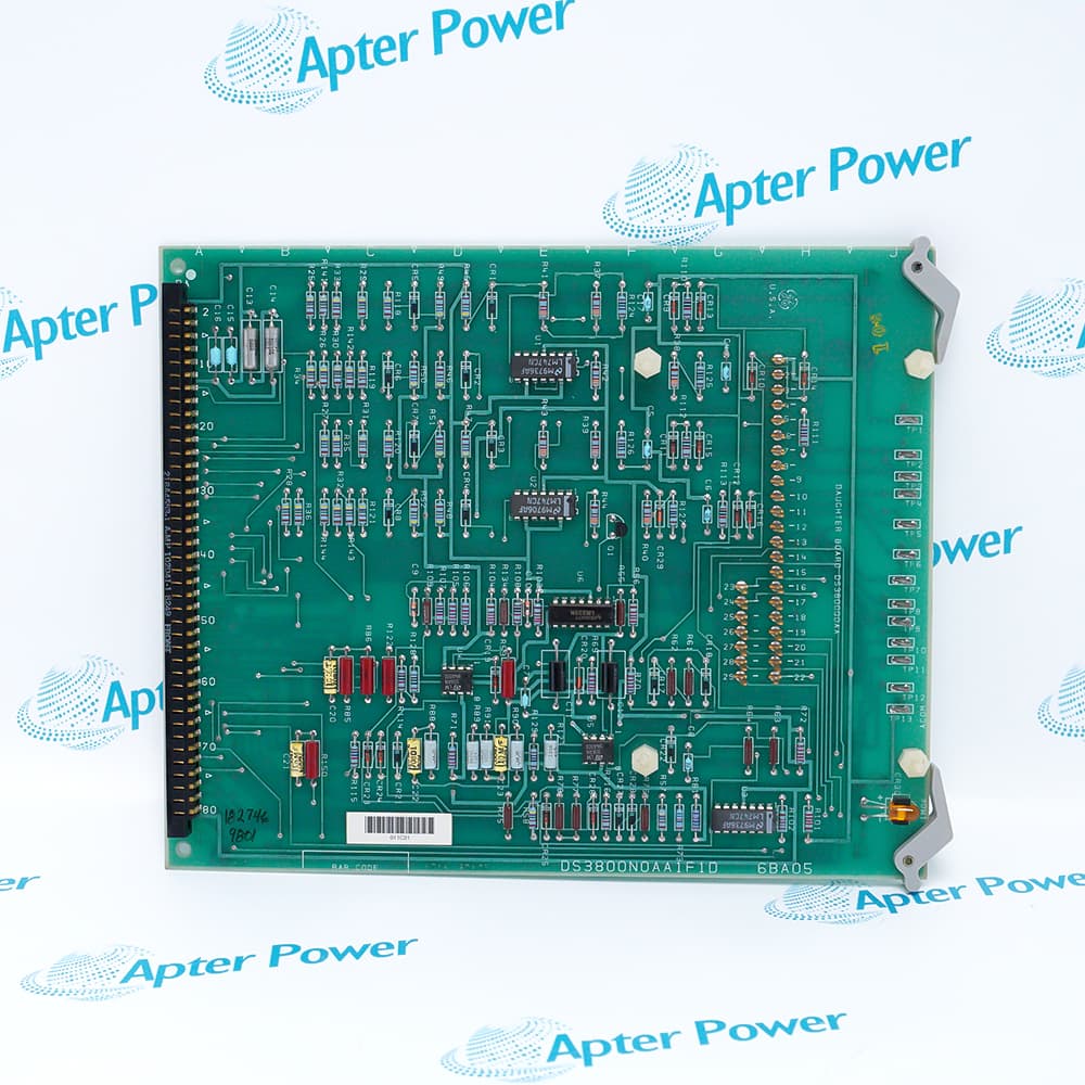
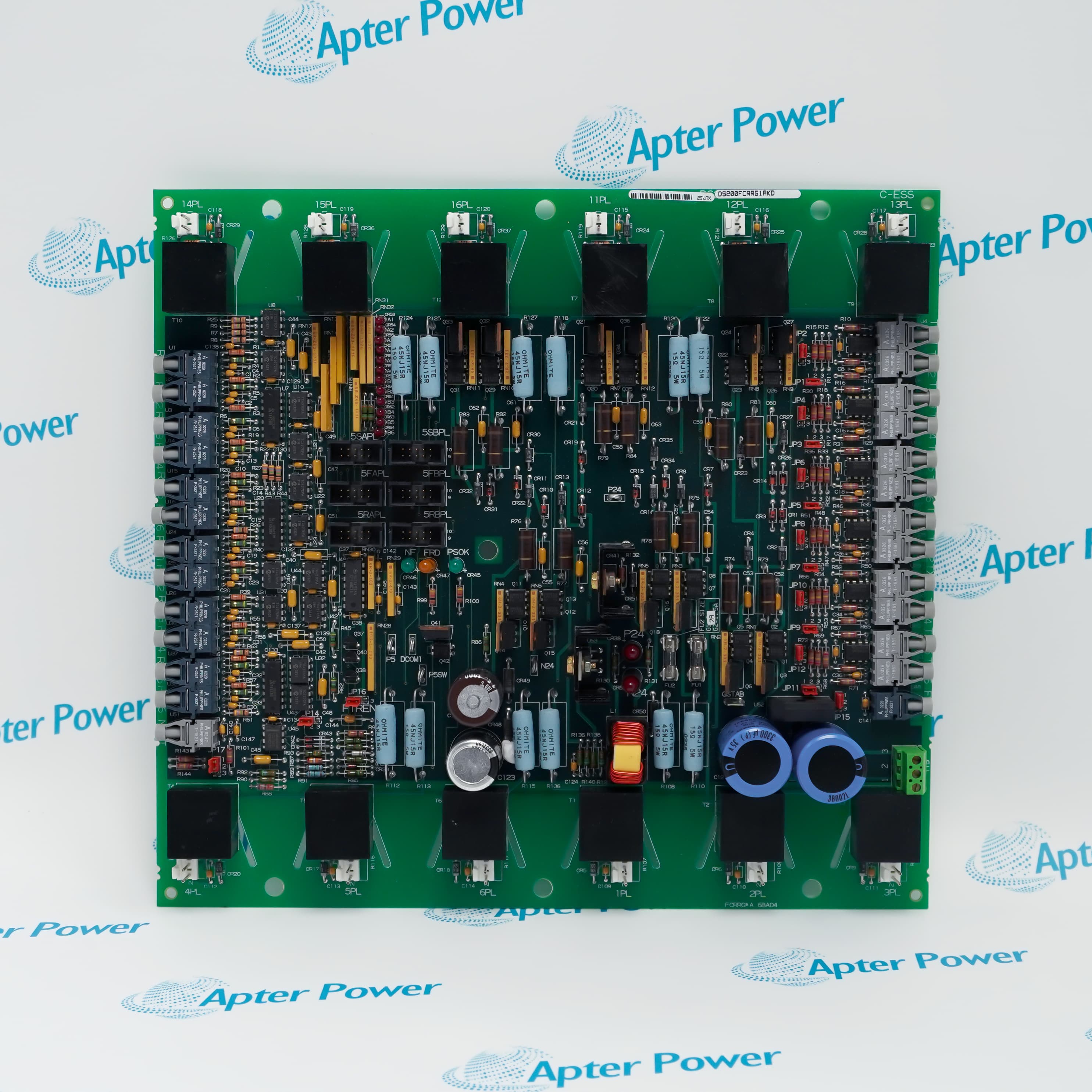
General Electric DS200TBQBG1A is the Mark V LM TBQB input termination module for voltage, vibration, pulse-rate, and compressor-stall signals routed to TCQA and TCQC.
In Stock
Ships by Thursday, October 29
Fast Shipping Available
Get a quick price for DS200TBQBG1A
Quantity
*E-mail
Company
*Mobile
*Content
Upload (gif, jpg, jpeg, png, bmp, doc, docx, xls, xlsx, ppt, pdf, csv)

Technical specifications for DS200TBQBG1A

  • Manufacturer:
    General Electric
  • Part Number:
    DS200TBQBG1A
  • Product Family:
    GE Mark V/VI Driver Board
  • Product Type:
    Input Termination Module
  • Stock:
    1
  • Module Type:
    Voltage, vibration, and pulse input termination
  • Core Position:
    Location 7 in R2 or R3
  • Processing Links:
    JGR to TCQA; JHR to TCQC
  • Input Selection:
    BJ8-BJ15 select current or voltage
  • Tariff Code:
    8536909000
  • Country of origin:
    USA
  • Place of shipment:
    Xiamen,Fujian,China
By purchasing this item, you agree to the Terms & Conditions, ApterPower is not an authorized distributor for listed manufacturers or tradenames and therefore the manufacturer's warranty does not apply. All our products come with ApterPower's 1-year warranty.

More Information

Overview Manuals Signal Inputs Core Links Jumper Options Fault Mapping

Features:

  • Accepts vibration, analog current, analog voltage, pulse-rate, and compressor-stall field inputs.
  • Separates JGR signals for TCQA from JHR signals for TCQC processing.
  • Provides BJ jumper choices for analog mode and the earlier pressure-transducer arrangement.
The mixed-input layout lets one terminal module serve several measurement classes while keeping their processing routes distinct.

A loss confined to JGR affects a different signal family from a loss confined to JHR, narrowing the shared fault boundary before individual field devices are examined.

The R2 installation crosses into R1 processing, whereas the R3 installation remains within R3, making core position a decisive part of cable restoration.

After manufacturer EOL, Apter Power continues quotation and documentation support for General Electric DS200TBQBG1A Input Termination Module.
General Electric DS200TBQBG1A Input Termination Module Manuals, Datasheets, Links Important Notice: Other accessories, manuals, cables, calibration data, software, etc. are not included with this equipment unless listed in the above stock item description. All prices are shown in USD.

DS200TBQBG1A Connector Signal Families

  • Vibration path: Vibration measurements leave the terminal module through JGR for TCQA processing.
  • Analog path: Current and voltage field signals share JGR but retain their selected electrical mode.
  • Pulse path: Pulse-rate inputs use JHR and are received by TCQC rather than TCQA.
  • Stall path: Compressor-stall pressure inputs also use JHR, keeping them with the TCQC signal group.

Location Seven Processing Routes

  • R2 JGR route: The DS200TBQBG1A in the R2 core sends its JGR group to TCQA in the R1 core.
  • R2 JHR route: Pulse-rate and compressor-stall signals from the R2 position continue to TCQC in R1.
  • R3 JGR route: The R3 installation sends vibration and analog measurements to TCQA in the R3 core.
  • R3 JHR route: JHR from the R3 position terminates at TCQC in that same core.

DS200TBQBG1A BJ Selection Logic

  • BJ8-BJ15: Each jumper selects current or voltage operation for its associated analog input.
  • BJ1-BJ4: These positions fan out compressor-stall pressure-transducer input 1 in the earlier arrangement.
  • BJ5-BJ7: The burden-resistor selection converts the older pressure input from voltage to current operation.
  • Mode consequence: A jumper that does not match the field source can produce an incorrect value even when the sensor and cable are intact.

Separating DS200TBQBG1A Input Faults

  • JGR-wide symptom: Simultaneous vibration and analog losses point toward the grouped cable or TCQA destination.
  • JHR-wide symptom: Pulse-rate and compressor-stall losses together direct attention to the JHR or TCQC path.
  • Scaling symptom: A valid signal with the wrong magnitude can result from an incorrect BJ current-or-voltage selection.
  • Unused connectors: JGS, JGT, JHS, and JHT should not be assigned a function without a cabinet-specific drawing.
Description
At location seven in either the R2 or R3 Mark V LM analog core, General Electric DS200TBQBG1A serves as the TBQB input termination module for voltage, vibration, pulse-rate, and compressor-stall field signals.

Two connector families separate the processing destinations on DS200TBQBG1A. JGR carries vibration measurements together with analog current and voltage inputs to TCQA, while JHR carries pulse-rate and compressor-stall inputs to TCQC.

Input mode selection is concentrated in the BJ jumper bank. On DS200TBQBG1A, BJ8 through BJ15 select current or voltage operation, while BJ1 through BJ7 support the older pressure-transducer fan-out and burden-resistor arrangement for compressor-stall input 1.

JGS, JGT, JHS, and JHT are normally unused in this arrangement. The installed R2 or R3 position, the JGR and JHR destinations, and the retained BJ pattern together define how DS200TBQBG1A presents each field signal to the control system.
Alternative Names
DS200-TBQB-G1A DS200 TBQB G1A GE DS200TBQBG1A GE Mark V DS200TBQBG1A DS200TBQB G1A DS2O0TBQBG1A DS200TBQBGIA DS200TBQBG1A-GE
Technical notes
For DS200TBQBG1A, record the R2/R3 position and BJ1-BJ15 pattern; JGR and JHR terminate at different processing boards.
Exceptional Service

Our Mission

  • 100% Satisfaction

    We believe expertise is priceless. With over 20 years of experience, and top engineers on staff, we can help you solve or avoid problems that threaten your business.
  • Trust Guaranteed

    Not only do we have a vast inventory, our team makes sure every piece of equipment is in working condition. Your purchases are also backed by our Warranty.
  • Expertise

    Time is money, especially when your equipment is down. We work quickly to get your equipment on its way so you can get it back up and running.

FAQS

The following is a list of questions commonly asked by our customers. Please contact us if you have a question about our process that is not answered below.
Why can DS200TBQBG1A vibration and analog readings fail together?
DS200TBQBG1A places vibration plus analog current and voltage signals on JGR, so a shared JGR cable or TCQA path can affect those measurements together.
Why can DS200TBQBG1A pulse-rate inputs fail while JGR signals remain normal?
DS200TBQBG1A routes pulse-rate and compressor-stall inputs on JHR to TCQC, a different path from the JGR signals sent to TCQA.
What causes a DS200TBQBG1A analog channel to read incorrectly after replacement?
An incorrect BJ8-BJ15 setting on DS200TBQBG1A can select current when the field source is voltage, or voltage when the source is current.
When do the DS200TBQBG1A BJ1-BJ7 jumpers matter?
On DS200TBQBG1A they apply to older compressor-stall pressure-transducer input 1 arrangements, including signal fan-out and the burden resistor for current operation.
Why must the core position be recorded for DS200TBQBG1A?
The DS200TBQBG1A in R2 connects to processing boards in R1, whereas the R3 installation connects to boards in R3; swapping those destinations breaks the documented signal path.
Should DS200TBQBG1A unused connectors be populated during replacement?
JGS, JGT, JHS, and JHT are normally unused on DS200TBQBG1A, so any connected circuit should be checked against the cabinet drawing before it is treated as intentional.
How should DS200TBQBG1A be checked after jumper or wiring work?
Stimulate each disturbed DS200TBQBG1A input, confirm the selected current or voltage mode, and verify that JGR data reaches TCQA while JHR data reaches TCQC.

Product Browsing History