Ask our team:
  • Phone: +86 181 0690 9650
  • E-Mail info@apterpower.com
  • Lifecycle status

    Discontinued / Obsolete by OEM
    Request a quotation, documentation support and M-frame system matching for General Electric DS200SHVMG1A.

DS200SHVMG1A

/ 4.9
1001 reviews | Need a Specific Revision?
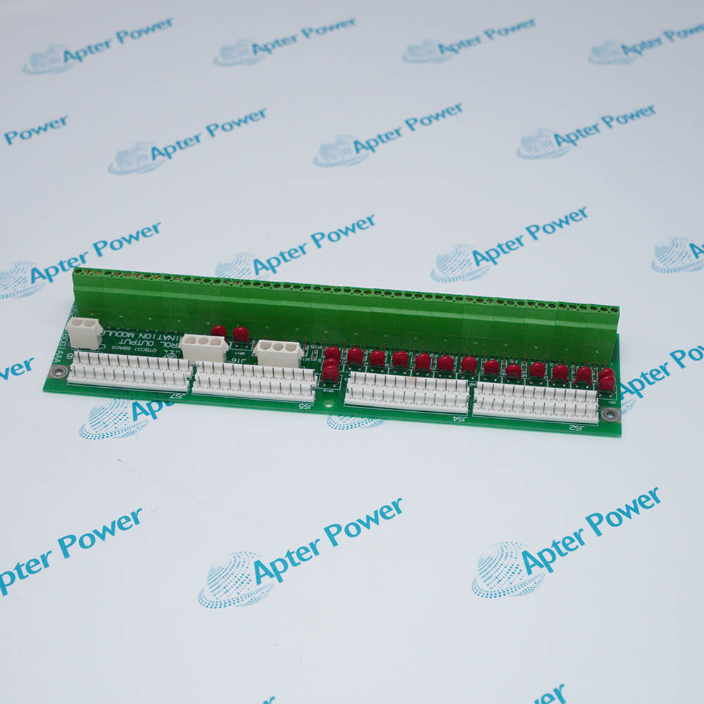
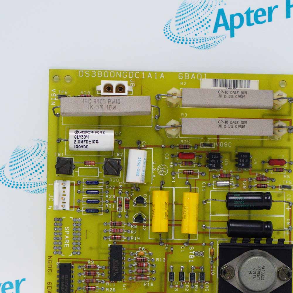
General Electric DS200SHVMG1A is an SCR High Voltage M-Frame Interface Board that connects M-frame bridge feedback to DC2000 drive control boards.
In Stock
Ships by Tuesday, September 29
Fast Shipping Available
Get a quick price for DS200SHVMG1A
Quantity
*E-mail
Company
*Mobile
*Content
Upload (gif, jpg, jpeg, png, bmp, doc, docx, xls, xlsx, ppt, pdf, csv)

Technical specifications for DS200SHVMG1A

  • Manufacturer:
    General Electric
  • Part Number:
    DS200SHVMG1A
  • Product Family:
    GE Mark V/VI Driver Board
  • Product Type:
    SCR High Voltage M-Frame Interface Board
  • Stock:
    1
  • Board Function:
    High-voltage measurement interface
  • System:
    DC2000 M-frame drives
  • Signal Conversion:
    DC shunt input to differential frequency output
  • Shunt Input Range:
    Approximately -500 to +500 mV
  • Frequency Output:
    0 to 500 kHz
  • AC Line Current Scaling:
    Selectable 10:1 CT attenuation
  • Voltage Range Setup:
    240-600 VAC bypass; 601-1000 VAC attenuation
  • Board Interfaces:
    DCFB or SDCI control board and PCCA card
  • Configurable Hardware:
    17 jumpers, JP1-JP17
  • Tariff Code:
    8537101190
  • Country of origin:
    USA
  • Place of shipment:
    Xiamen,Fujian,China
By purchasing this item, you agree to the Terms & Conditions, ApterPower is not an authorized distributor for listed manufacturers or tradenames and therefore the manufacturer's warranty does not apply. All our products come with ApterPower's 1-year warranty.

More Information

Overview Manuals Signal Paths Voltage Setup Board Links Jumper Plan

Features:

  • Translates floating bridge-shunt feedback into differential pulse streams.
  • Applies selectable scaling to line-current and high-voltage measurement paths.
  • Links M-frame power hardware with DCFB or SDCI and PCCA electronics.
Signal conversion on DS200SHVMG1A keeps the positive and negative current channels distinct. Each VCO develops a frequency proportional to its low-level shunt input for use by the downstream controller.

The line-current branch on DS200SHVMG1A can introduce 10:1 attenuation before the measurement leaves the board. This selection accommodates the documented current-transformer signal range without changing the control-card interface.

Separate source and converter monitoring branches on DS200SHVMG1A use range jumpers to choose either a direct measurement path or additional attenuation according to the M-frame drive voltage.

The General Electric DS200SHVMG1A SCR High Voltage M-Frame Interface Board may still be available for purchase and support from Apter Power beyond End-Of-Life (EOL) by the manufacturer (OEM).
General Electric DS200SHVMG1A SCR High Voltage M-Frame Interface Board Manuals,Datasheets,Link Important Notice: Other accessories, manuals, cables, calibration data, software, etc. are not included with this equipment unless listed in the above stock item description. All prices are shown in USD.

Current Feedback Chain

  • Shunt Channels: Positive and negative floating shunt inputs remain separate.
  • VCO Stage: Voltage-controlled oscillators translate millivolt feedback to pulse frequency.
  • Output Form: Differential frequency signals extend from 0 to 500 kHz.
  • Destination: Converted current feedback proceeds to the DCFB or SDCI control path.

Scaling Selection

  • Low Range: The attenuation network is bypassed for 240-600 VAC equipment.
  • High Range: Additional attenuation is inserted for 601-1000 VAC operation.
  • Line Current: A selectable 10:1 CT path changes AC current scaling.
  • Setup Rule: Voltage and current choices must agree with the installed drive rating.

Control Connections

  • Controller Side: The board interfaces with either a DCFB or an SDCI control board.
  • Power Side: PCCA provides the associated power-connect interface.
  • Measured Points: Line, motor and SCR bridge voltages use dedicated paths.
  • Frame Limit: This SHVM group is assigned to DC2000 M-frame hardware.

Hardware Configuration

  • Jumper Bank: Seventeen positions, JP1 through JP17, define board options.
  • Range Choice: Several positions select voltage attenuation or bypass.
  • Current Choice: The CT branch has its own scaling selection.
  • Commissioning Boundary: The complete pattern must match the cabinet drawing and drive nameplate.
Description
Within a DC2000 M-frame power cabinet, DS200SHVMG1A occupies the high-voltage feedback boundary between the SCR bridge and the low-voltage DCFB or SDCI control electronics. Its measurement paths are coordinated with the PCCA connection so the drive controller can evaluate bridge current and voltage.

DS200SHVMG1A accepts floating DC shunt signals in the approximately -500 to +500 mV range and converts them through voltage-controlled oscillator circuits into differential frequency outputs. This conversion provides an isolated signal path for positive and negative shunt feedback.

DS200SHVMG1A also handles AC line-current information and voltage monitoring for the incoming line, motor, and SCR bridge. A selectable 10:1 current-transformer attenuation path and separate voltage-scaling paths adapt the measured signals to the receiving control hardware.

DS200SHVMG1A uses configurable jumpers to match voltage range and circuit arrangement. The voltage attenuation path is bypassed for 240-600 VAC operation and inserted for 601-1000 VAC operation, so the installed jumper pattern must match the drive rating and board connections.
Revisions

Revision Part #

Also known as

DS200SHVMG1ACD
DS200SHVMG1A-CD, Series CD, Rev CD
Alternative Names
GE DS200SHVMG1A DS200-SHVM-G1A DS 200 SHVM G1A DS200SHVMG1A M-frame board General Electric SHVM interface card DC2000 M-frame high-voltage interface GE SHVM G1A DS2OOSHVMG1A
Exceptional Service

Our Mission

  • 100% Satisfaction

    We believe expertise is priceless. With over 20 years of experience, and top engineers on staff, we can help you solve or avoid problems that threaten your business.
  • Trust Guaranteed

    Not only do we have a vast inventory, our team makes sure every piece of equipment is in working condition. Your purchases are also backed by our Warranty.
  • Expertise

    Time is money, especially when your equipment is down. We work quickly to get your equipment on its way so you can get it back up and running.

FAQS

The following is a list of questions commonly asked by our customers. Please contact us if you have a question about our process that is not answered below.
Why does DS200SHVMG1A show no usable current-feedback signal after installation?
Check that DS200SHVMG1A receives the floating shunt input and that its differential frequency output reaches the DCFB or SDCI path; an open input or disconnected output prevents the controller from seeing bridge current.
How should a scaling mismatch on DS200SHVMG1A be investigated?
When DS200SHVMG1A feedback appears compressed or overrange, inspect the voltage-scaling jumper bank and compare it with the drive nameplate band before tracing downstream wiring.
What can cause AC line-current readings from DS200SHVMG1A to be scaled incorrectly?
DS200SHVMG1A provides selectable 10:1 current-transformer attenuation. Verify the attenuation setting against the installed CT and the receiving control board when readings are consistently high or low.
Can DS200SHVMG1A be used in a non-M-frame DC2000 drive?
No. DS200SHVMG1A is designated for M-frame drives, so confirm the frame and the DCFB or SDCI/PCCA interface before integrating the board.
Why might positive and negative shunt feedback from DS200SHVMG1A behave differently?
DS200SHVMG1A uses separate voltage-controlled oscillator paths for the floating positive and negative shunts. Check both input polarities, both frequency-output paths, and their destination connections.