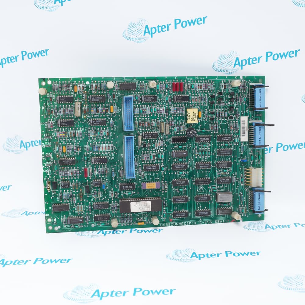
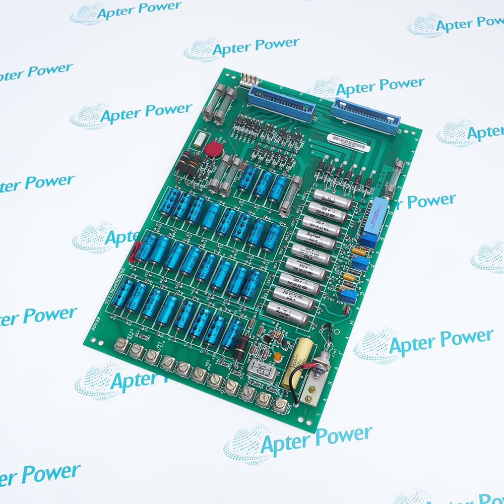
Features:
- Supports 16 Form-C (SPDT) Relays For Precise Field Device Control.
- Operates With 24 VDC Coil Voltage And +5 VDC Logic Supply With 1500 V RMS Isolation.
- Built For Industrial Environments With –20 °C To +60 °C Operation And 5%–95% Non-Condensing Humidity.
The General Electric DS200TCRAG1ACC is a specialized relay output board tailored for industrial turbine and drive control systems. Within the Mark V architecture, the General Electric DS200TCRAG1ACC plays a vital role in translating digital commands into actionable outputs. Its design emphasizes reliability and precision, making it suitable for mission-critical environments where consistent performance is required. The ability to handle both high and low switching loads ensures adaptability across various industrial scenarios. Furthermore, the General Electric DS200TCRAG1ACC contributes to maintaining stable system operations by ensuring accurate signal execution.
From a hardware perspective, the General Electric DS200TCRAG1ACC integrates robust relay components with high electrical endurance. Its Form-C relay configuration allows flexible switching logic, accommodating different operational requirements. The board’s electrical specifications, including its 5 A contact rating and 24 VDC coil voltage, align with common industrial standards. This ensures that the General Electric DS200TCRAG1ACC can be easily incorporated into existing infrastructures without requiring extensive modifications. Additionally, its strong isolation capability enhances operational safety and protects connected equipment.
In practical applications, the General Electric DS200TCRAG1ACC is widely used in gas turbine control, drive systems, and other automated processes requiring reliable output control. Its compatibility with Mark V system modules enables coordinated operation across multiple control layers. The design also supports efficient maintenance through pluggable relays and accessible connectors, minimizing service time. Overall, the General Electric DS200TCRAG1ACC delivers a balanced combination of durability, flexibility, and performance, making it a dependable choice for industrial automation environments.
The DS200TCRAG1ACC General Electric Relay Output Board may still be available for purchase and support from Apter Power beyond End-Of-Life (EOL) by the manufacturer (OEM).
General Electric DS200TCRAG1ACC Relay Output Board Manuals,Datasheets,Link
Important Notice: Other accessories, manuals, cables, calibration data, software, etc. are not included with this equipment unless listed in the above stock item description. All prices are shown in USD.
General Electric DS200TCRAG1ACC Relay Output Board Specs
General
- Manufacturer General Electric
- Model DS200TCRAG1ACC
- Condition New Original ready stock
- Product Family DS200SLCCG1AEE,DS200RTBAG2AFB,DS200TCPDG1BEC
Important Notice: Other accessories, manuals, cables, calibration data, software, etc. are not included with this equipment unless listed in the above stock item description. All prices are shown in USD.
- Temperature Control: The operating environment temperature should be maintained between 0°C and 50°C. Although this board is designed for industrial use, excessively high temperatures will accelerate relay contact oxidation and electrolytic capacitor aging.
- Humidity and Condensation: Relative humidity should be between 5% and 95% (non-condensing). High humidity environments must be avoided to prevent short circuits due to insufficient creepage distance on the circuit board.
- Electromagnetic Environment: It must be installed in a well-shielded control cabinet, away from high-voltage frequency converters or large motors, to prevent electromagnetic interference (EMI) from causing relay malfunctions.
- Vibration Protection: Mark V systems are typically installed in a control room on a fixed foundation. If installed near a skid, ensure the cabinet has vibration damping measures to prevent relay contacts from vibrating.
- Electrostatic Discharge (ESD) Protection: This board contains sensitive CMOS chips. Installers must wear anti-static wrist straps and be grounded. Direct contact with the solder joints on the back of the board is strictly prohibited.
- Connector Identification: Confirm that the four 34-pin connectors and four 12-pin connectors on the board are correctly inserted. The ACC version has specific revision marks; ensure the cable connectors are fully locked and not misaligned.
- Relay Self-Test: Before installation, check that the 30 onboard relays are securely inserted into their bases. Loose relays during transport can cause open circuits or unreliable outputs.
- Hardware Jumper Settings: Verify the jumper positions on the board according to the system design manual. Different jumper settings determine whether the relays are used for alarm signals or to directly drive actuators.
- Gas Turbine Start/Stop Logic: Controls the starter motor, auxiliary lubrication pump, and fuel system shut-off valves via the 30 relay outputs.
- Solenoid Valve Drive Control: Directly drives pneumatic or hydraulic solenoid valves around the turbine, such as bleed valves regulating the fuel manifold.
- System Fault Alarm: Converts the internal logic state of the Mark V system into dry contact outputs and sends them to the Central Control Room (CCR) or remote monitoring system.
- Emergency Trip System (ETS): In some configurations, this board participates in the protection circuit. When abnormalities such as overspeed or overtemperature are detected, it quickly disconnects the control power supply to trigger a shutdown.