Ask our team:
  • Phone: +86 181 0690 9650
  • E-Mail sales1@apterpower.com
  • Lifecycle status

    Active / Available from OEM
    Apter Power can prepare IS220PAICH1B pricing and provide access to official General Electric analog I/O documentation for project checks.

IS220PAICH1B

/ 4.9
1001 reviews | Need a Specific Revision?
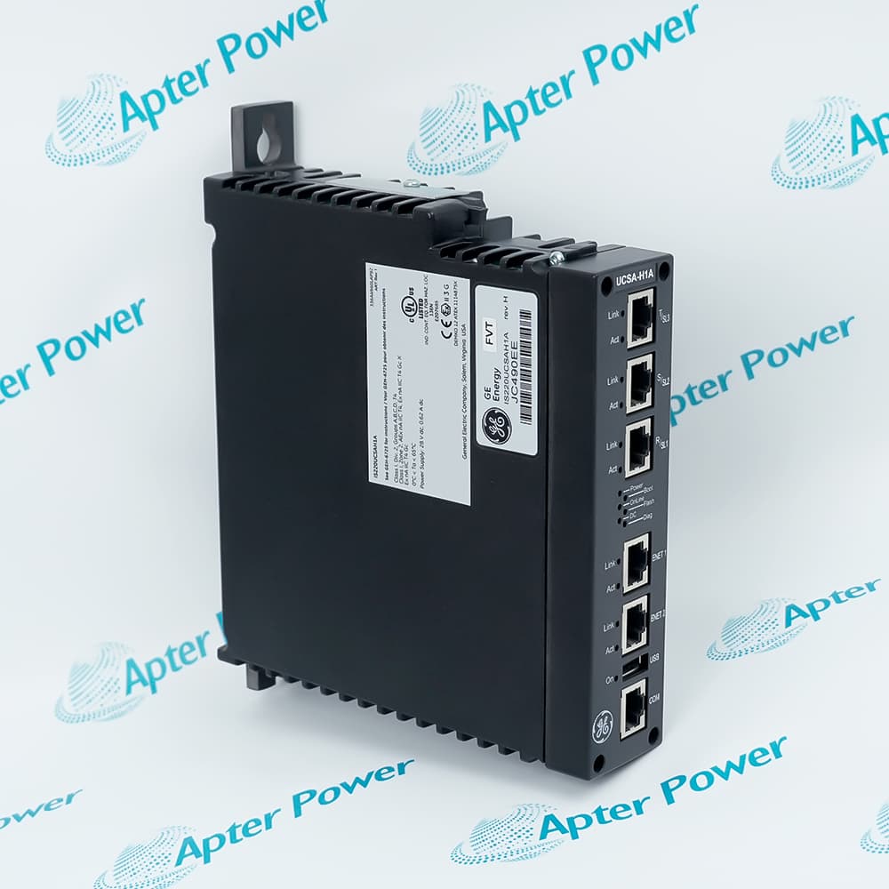
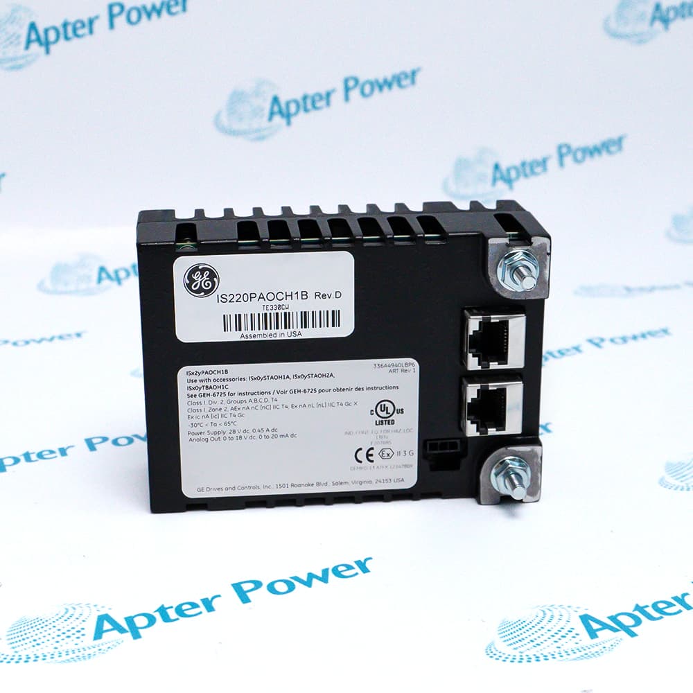
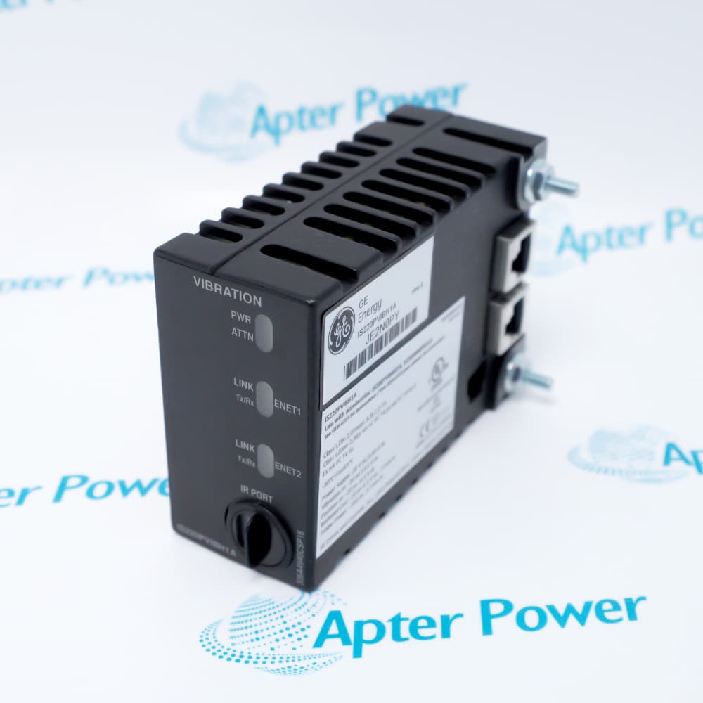
The General Electric IS220PAICH1B Mark VIe analog I/O module with ten inputs and two outputs connects mixed field measurements and command signals to turbine-control cabinets.
In Stock
Ships by Wednesday, October 28
Fast Shipping Available
Get a quick price for IS220PAICH1B
Quantity
*E-mail
Company
*Mobile
*Content
Upload (gif, jpg, jpeg, png, bmp, doc, docx, xls, xlsx, ppt, pdf, csv)

Technical specifications for IS220PAICH1B

  • Manufacturer:
    General Electric
  • Part Number:
    IS220PAICH1B
  • Product Family:
    GE Mark VIe Distributed I/O
  • Product Type:
    Mark VIe analog I/O module with ten inputs and two outputs
  • Stock:
    1
  • Supply input:
    24–28 V dc
  • Maximum input current:
    0.49 A
  • Analog inputs:
    10 channels
  • Analog outputs:
    2 channels
  • Input channels 1–8 voltage:
    -10 to +10 V dc
  • Input channels 1–8 current:
    0 to 20 mA dc
  • Input channels 9–10 voltage:
    -5 to +5 V dc
  • Input channels 9–10 current:
    -1 to 20 mA dc
  • Analog output voltage:
    0 to 16.3 V dc
  • Analog output current:
    0 to 20 mA dc
  • Analog transmitter power:
    24 V dc, 21 mA dc
  • Compatible terminal boards:
    STAIH1A, STAIH2A, and TBAIH1C families
  • RoHS acquisition boards:
    IS400BPAIH1A or IS400BPAIH2A
  • Required enclosure rating:
    Minimum IP54 for classified-location installation
  • Pollution degree:
    Not more than Pollution Degree 2
  • Transient protection:
    Limit supply transients to no more than 140% of peak rated voltage
  • Tariff Code:
    8538900000
  • Country of origin:
    USA
  • Place of shipment:
    Xiamen,Fujian,China
By purchasing this item, you agree to the Terms & Conditions, ApterPower is not an authorized distributor for listed manufacturers or tradenames and therefore the manufacturer's warranty does not apply. All our products come with ApterPower's 1-year warranty.

More Information

Overview Manuals Signal Ranges Terminal Pairing Installation Controls Loop Checks

Features:

  • Brings voltage, current-loop, and analog command channels together in one distributed I/O pack.
  • Works through an approved terminal board so field wiring remains separated from the replaceable electronics.
  • Provides a defined replacement boundary for mixed analog loops in turbine and industrial control cabinets.
The channel arrangement helps a service team group related process signals while still respecting the different ranges assigned to the first eight inputs and the final two inputs.

Terminal-board selection is part of the hardware identity. A replacement check therefore includes both the I/O pack label and the board that carries the field connections.

When the surrounding enclosure and power path meet the certified conditions, the module can be integrated into the distributed Mark VIe architecture without changing the basic field-loop concept.

Apter Power can assist with quotation, exact-model review, and sourcing for the General Electric IS220PAICH1B Mark VIe analog I/O module with ten inputs and two outputs.
General Electric IS220PAICH1B Mark VIe analog I/O module with ten inputs and two outputs Manuals, Datasheets, Links Important Notice: Other accessories, manuals, cables, calibration data, software, etc. are not included with this equipment unless listed in the above stock item description. All prices are shown in USD.

Channel ranges used by IS220PAICH1B

  • Inputs 1–8: Accept -10 to +10 V dc or 0 to 20 mA dc within the certified assembly.
  • Inputs 9–10: Cover -5 to +5 V dc or -1 to 20 mA dc.
  • Analog command voltage: The output path is listed for 0 to 16.3 V dc.
  • Analog command current: The corresponding current range is 0 to 20 mA dc.
  • Transmitter feed: The field supply is rated at 24 V dc and 21 mA.
  • Configuration check: The physical loop and software range must describe the same signal before commissioning.

Approved hardware relationships for IS220PAICH1B

  • Compact terminal option: STAIH1A and STAIH2A families are listed with this analog I/O pack.
  • Barrier-style option: The TBAIH1C family is also identified as compatible.
  • RoHS construction: IS400BPAIH1A or IS400BPAIH2A may form the internal acquisition assembly.
  • Field-side match: RoHS terminal constructions include the corresponding IS400 STAI and TBAI boards.
  • Replacement rule: Read the full terminal-board code instead of assuming every PAIC installation uses the same landing hardware.

Certified installation conditions for IS220PAICH1B

  • Power window: Supply the module with 24–28 V dc and provide for a maximum input of 0.49 A.
  • Enclosure: Classified-location use requires a suitable enclosure providing at least IP54 protection.
  • Pollution environment: The installed location must not exceed Pollution Degree 2.
  • Transient control: Protection must keep supply transients within 140% of the peak rated voltage.
  • Power distribution: Use the certified distribution and switched-mode supply arrangement required for the applicable location.

Commissioning checks for IS220PAICH1B

  • Before energizing: Compare the pack, terminal-board, and cabinet wiring designations with the control project.
  • Input verification: Apply a test value that stays inside the range assigned to the channel group being checked.
  • Transmitter loops: Confirm the 24 V dc field supply and load path before treating a zero reading as an I/O-pack fault.
  • Output verification: Check polarity and receiving-device loading before issuing a controlled analog command.
  • Return to service: Restore loops one group at a time and confirm the engineering-unit response at the controller.
Description
Ten analog inputs and two analog outputs are handled locally by the General Electric IS220PAICH1B Mark VIe Analog I/O Module. Its acquisition and output paths are organized around compatible terminal-board families so mixed process measurements and controlled analog outputs can share one distributed interface.

Across the first eight channels, IS220PAICH1B accepts the standard voltage or current ranges used by common transmitters. Channels nine and ten use their own channel-specific limits, so a loop migration should preserve each channel assignment instead of applying one scaling rule across all ten inputs.

Dual Ethernet ports and the dedicated dc supply place IS220PAICH1B on the Mark VIe network, while field wiring remains on the selected STAI or TBAI terminal board. A processor-pack exchange can therefore retain established terminations, provided the terminal-board designation, network connections, power path, and configured ranges are checked together.

Before commissioning IS220PAICH1B, confirm enclosure conditions, transmitter-power routing, output-loop loading, and the project configuration in ToolboxST. These checks connect the replacement to the actual cabinet wiring and control database rather than treating the module as a generic analog interface.
Revisions

Revision Part #

Also known as

IS220PAICH1B
IS220PAICH1-B, Series B, Rev B
IS220PAICH1A
IS220PAICH1-A, Series A, Rev A
Alternative Names
IS220 PAIC H1B IS 220 PAIC H1B IS220-PAICH1B IS220PAIC-H1B GE IS220PAICH1B GE IS220 PAIC H1B PAICH1B analog I/O pack IS220PAICHIB
Technical notes
For IS220PAICH1B loop checks, inputs 1–8 and inputs 9–10 have different permitted voltage and current ranges; verify the configured channel before applying a test source.
Exceptional Service

Our Mission

  • 100% Satisfaction

    We believe expertise is priceless. With over 20 years of experience, and top engineers on staff, we can help you solve or avoid problems that threaten your business.
  • Trust Guaranteed

    Not only do we have a vast inventory, our team makes sure every piece of equipment is in working condition. Your purchases are also backed by our Warranty.
  • Expertise

    Time is money, especially when your equipment is down. We work quickly to get your equipment on its way so you can get it back up and running.

FAQS

The following is a list of questions commonly asked by our customers. Please contact us if you have a question about our process that is not answered below.
Which terminal boards can be paired with IS220PAICH1B?
Use the approved STAIH1A, STAIH2A, or TBAIH1C terminal-board family identified for IS220PAICH1B. Confirm the exact IS200 or IS400 assembly marking before moving field wiring.
Why can channels 9 and 10 on IS220PAICH1B show an unexpected value after replacement?
On IS220PAICH1B, channels 9 and 10 use different input limits from channels 1 through 8. Verify the configured range against the connected signal before troubleshooting an apparent scaling error.
What supply should be checked before installing IS220PAICH1B?
Measure 24–28 V dc at the approved power path and allow for the 0.49 A maximum input stated for IS220PAICH1B. Correct the supply condition before connecting field circuits.
Can IS220PAICH1B be installed without a protective enclosure in a classified area?
Install IS220PAICH1B only in an enclosure that maintains the specified ambient and protection conditions. Check cabinet ventilation and the local temperature before returning the I/O node to service.
What should be compared before a like-for-like IS220PAICH1B exchange?
During an IS220PAICH1B exchange, retain the field wiring on the compatible terminal board, verify both Ethernet connections and the dc supply, then confirm the correct ToolboxST configuration.
Why might transmitter power be missing on an IS220PAICH1B input loop?
IS220PAICH1B can provide transmitter excitation through the supported terminal-board arrangement, but the assignment must match the wiring and channel configuration. Measure the excitation at the terminal board if a loop remains inactive.
What should be checked when an IS220PAICH1B analog output does not respond?
Use the IS220PAICH1B analog output only with the approved load and range. If the command is correct but the field signal is not, inspect the terminal-board circuit, loop load, and output configuration in that order.