Ask our team:
  • Phone: +86 181 0690 9650
  • E-Mail sales1@apterpower.com
  • Lifecycle status

    Discontinued / Obsolete by OEM
    Apter Power supports 469-P5-HI-A1 documentation, sourcing, quotation and legacy-system planning.

469-P5-HI-A1

/ 4.9
1001 reviews | Need a Specific Revision?
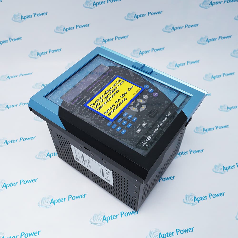
GE Multilin 469-P5-HI-A1 is a motor management relay configured for 5 A phase-CT secondaries, high-range control power and 0–1 mA analog outputs.
In Stock
Ships by Wednesday, October 28
Fast Shipping Available
Get a quick price for 469-P5-HI-A1
Quantity
*E-mail
Company
*Mobile
*Content
Upload (gif, jpg, jpeg, png, bmp, doc, docx, xls, xlsx, ppt, pdf, csv)

Technical specifications for 469-P5-HI-A1

  • Manufacturer:
    General Electric
  • Part Number:
    469-P5-HI-A1
  • Product Family:
    GE Multilin
  • Product Type:
    Motor Management Relay
  • Stock:
    1
  • Series:
    Multilin 469
  • Phase CT option:
    P5, 5 A secondary
  • Control power:
    HI, 90–300 VDC / 70–265 VAC
  • Analog output option:
    A1, 0–1 mA
  • Weight:
    4.94 kg
  • Estimated shipping dimensions:
    18.5x18x23cm
  • Tariff Code:
    Please confirm the destination before shipping
  • Country of origin:
    USA
  • Place of shipment:
    Xiamen,Fujian,China
By purchasing this item, you agree to the Terms & Conditions, ApterPower is not an authorized distributor for listed manufacturers or tradenames and therefore the manufacturer's warranty does not apply. All our products come with ApterPower's 1-year warranty.

More Information

Overview Manuals Protection Logic Analog Output Integration Checks Product Applications

Features:

  • P5 input option for 5 A phase-CT secondaries.
  • HI control-power range covering 90–300 VDC or 70–265 VAC.
  • A1 analog-output option providing 0–1 mA signals.
The ordering code fixes the current-input, power-supply and analog-interface choices for this relay.

Protection performance also depends on the motor-specific settings stored for the installed application.

A replacement should not enter service until its option code, wiring and settings have been reconciled.
Availability is subject to Apter Power inventory and sourcing confirmation.
General Electric 469-P5-HI-A1 Motor Management Relay Manuals,Datasheets,Links

Important Notice: Other accessories, manuals, cables, calibration data, software, etc. are not included with this equipment unless listed in the above stock item description. All prices are shown in USD.

  • Uses the approved motor settings as the protection baseline.
  • Requires phase-CT circuits that match the P5 input option.
  • Preserves trip, alarm and restart decisions recorded for the motor.
  • Calls for a functional trip check before return to service.
  • A1 provides 0–1 mA analog outputs.
  • Connected receivers must accept the same signal range.
  • Output assignment and scaling should be copied from the approved record.
  • Unexpected readings should trigger a wiring and configuration review.
  • Confirm the HI control-power source before energizing the relay.
  • Verify CT polarity, ratios and terminal assignments.
  • Restore communications settings for the existing control network.
  • Document firmware and settings-file versions after commissioning.
  • Motor protection and management in established industrial systems.
  • Replacement of configured Multilin 469 relays.
  • Motor applications using 5 A CT secondaries.
  • Legacy protection spares and outage planning.
Description
Three interface decisions meet in 469-P5-HI-A1: the phase-current input, the relay’s control-power range and the analog-output format. Their combination places this Multilin 469 configuration at a specific boundary between the motor circuits and the plant monitoring system.

Motor-specific protection logic gives 469-P5-HI-A1 its operating purpose. Once the approved settings and CT relationships are loaded, the relay can evaluate the installed motor while presenting the selected analog signals to existing indicators or control-system inputs.

During a retrofit or spare exchange, 469-P5-HI-A1 preserves more than the trip function; it also preserves the expected current interface, power supply and analog signal path. That broader integration is why the full suffix set matters when comparing another Multilin 469 relay.
Alternative Names
GE 469-P5-HI-A1 Multilin 469-P5-HI-A1 469 P5 HI A1 469-P5-H1-A1 469-P5-HI-AI 469P5HIA1 GE Multilin 469 P5 469 motor management relay 469-P5-HI-A1 relay
Technical notes
P5 denotes 5 A phase-CT secondaries, HI denotes the 90–300 VDC or 70–265 VAC control-power range, and A1 denotes 0–1 mA analog outputs. Verify all three before replacement.
Exceptional Service

Our Mission

  • 100% Satisfaction

    We believe expertise is priceless. With over 20 years of experience, and top engineers on staff, we can help you solve or avoid problems that threaten your business.
  • Trust Guaranteed

    Not only do we have a vast inventory, our team makes sure every piece of equipment is in working condition. Your purchases are also backed by our Warranty.
  • Expertise

    Time is money, especially when your equipment is down. We work quickly to get your equipment on its way so you can get it back up and running.

FAQS

The following is a list of questions commonly asked by our customers. Please contact us if you have a question about our process that is not answered below.
Can a maintenance engineer load a saved settings file into 469-P5-HI-A1 before returning the motor to service?
Use EnerVista to upload the saved file, but keep the relay out of service until its motor data and enabled protection functions have been reviewed for the installed machine.
Can a commissioning technician communicate with 469-P5-HI-A1 from the front during an outage?
Yes. The front interface is a non-isolated RS232 port operating at 9600 baud; use the correct service lead and stop if the panel arrangement does not permit safe access.
Should a controls engineer connect 469-P5-HI-A1 directly to an existing 4–20 mA PLC input?
No. The A1 outputs are 0–1 mA, so a 4–20 mA input will not interpret them correctly. Use a matching receiving channel or an engineered signal converter.
Can an installer energize 469-P5-HI-A1 from an unidentified auxiliary supply during a retrofit?
No. Identify the source before wiring; the HI option accepts 90–300 VDC or 70–265 VAC. Stop if the measured supply is outside its applicable range.
After phase-current wiring is rebuilt, what should a protection engineer verify on 469-P5-HI-A1 before a test run?
Confirm that the 5 A phase-CT inputs and programmed CT ratios represent the installed transformers, then compare displayed current with the commissioning test values before enabling protection.
When 469-P5-HI-A1 reports an unexpected motor trip, where should a reliability engineer begin?
Begin with the relay's event record and measured motor data rather than changing setpoints immediately. Its diagnostic information can separate a process condition from a configuration problem.

You May Also Like

Product Browsing History