Features:
- Acquires forty 0–22 mA inputs through a triple modular redundant measurement structure.
- Validates the three internal slice results before transferring channel data to the Trusted controller.
- Separates field common from module electronics while recording channel events at millisecond resolution.
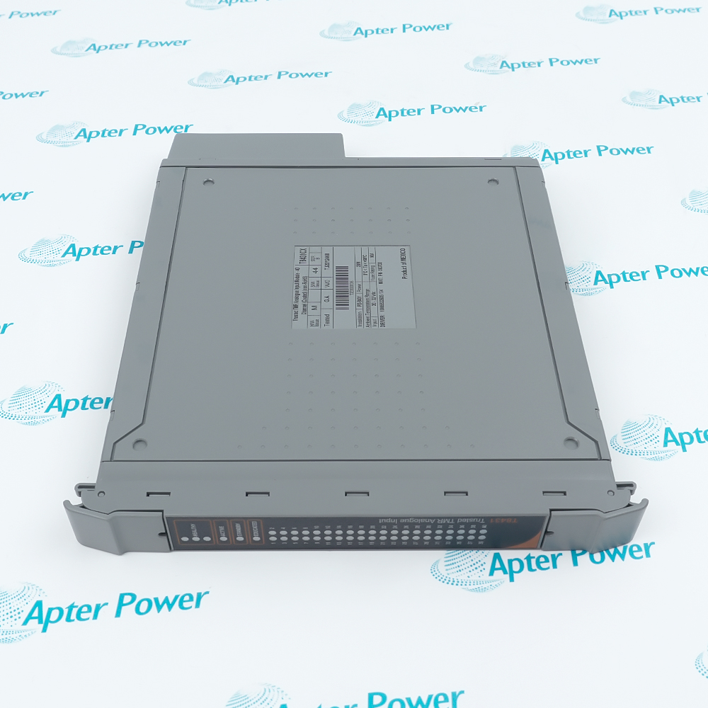
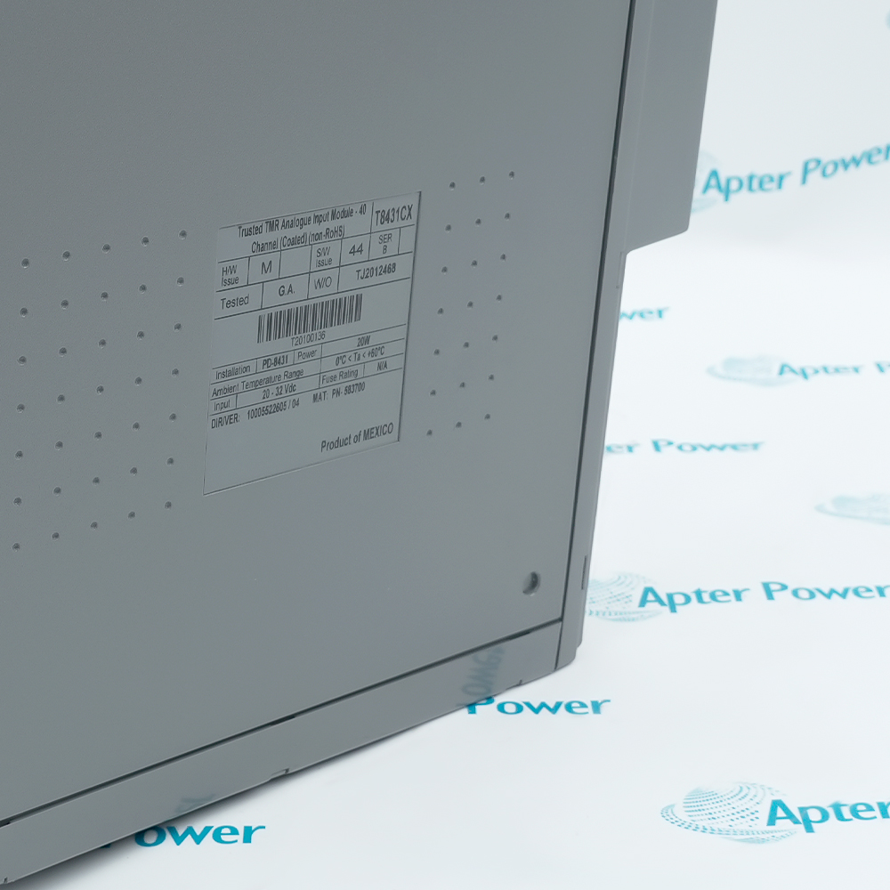
ICS Triplex T8431CX places forty analog inputs and three processing slices in one Trusted rack module.
Each slice measures the same field channels, and the validated result is accompanied by status and diagnostic information.
Shared channel reference, backplane power and the field termination arrangement define the external wiring boundary.
The ICS Triplex T8431CX Trusted TMR 40-Channel Analog Input Module may be available through Apter Power after OEM discontinuation, subject to exact configuration confirmation.
ICS Triplex T8431CX Trusted Analog Input Module Manuals,Datasheets,Link
Important Notice: Other accessories, manuals, cables, calibration data, software, etc. are not included with this equipment unless listed in the above stock item description. All prices are shown in USD.
Three-Slice Measurement Chain
- Field conversion: The field termination resistance converts each incoming current loop into a voltage for the input circuits.
- Parallel sampling: Three internal slices sample the same channel instead of assigning one slice to one group of inputs.
- Cross-check: The slice results are compared before the module accepts a channel value for transfer.
- Validated output: Only the validated measurement and its status move through the Trusted backplane to the controller.
- Range margin: The 0–22 mA measurement span includes the normal 4–20 mA signal and the configured out-of-range regions.
From Thresholds to Event Records
- Limit states: Configured thresholds classify the measured current without changing the underlying analog value.
- Fault distinction: Channel status separates an abnormal field signal from a disagreement detected inside the module.
- Event timing: A qualifying transition is entered in the sequence-of-events record with millisecond resolution.
- Front indication: Module and channel LEDs provide separate references for overall health and the affected input.
Rack and Field Termination Arrangement
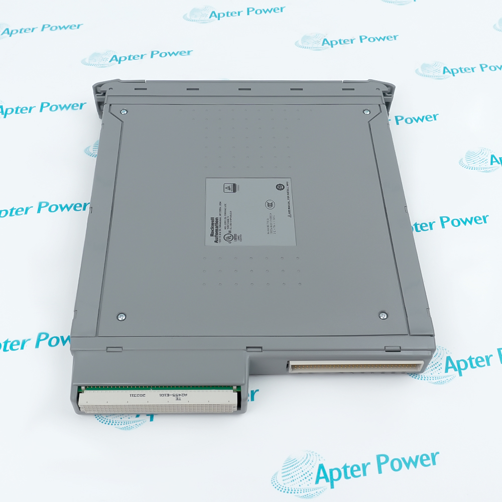
- Chassis connection: T8431CX occupies a Trusted chassis slot and receives its internal connection through the backplane.
- Loop landing: Forty field loops terminate through the assigned Trusted field termination assembly before reaching the module.
- Backplane power: The 20–32 V DC operating supply enters through the rack instead of being taken from an individual loop.
- Measurement setup: Resolution, calibration accuracy and threshold settings act on the converted value for each configured channel.
Isolation and Diagnostic Boundaries
- Slice disagreement: A mismatch between redundant measurements is diagnosed instead of being silently passed as process data.
- Field separation: Reinforced isolation separates field common from the internal module electronics.
- Shared reference: The forty inputs are not isolated from one another, so their field-side reference arrangement must be coordinated.
- Module reporting: Internal diagnostics and channel status travel with the validated data so the controller can distinguish their sources.