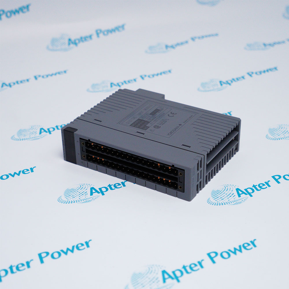
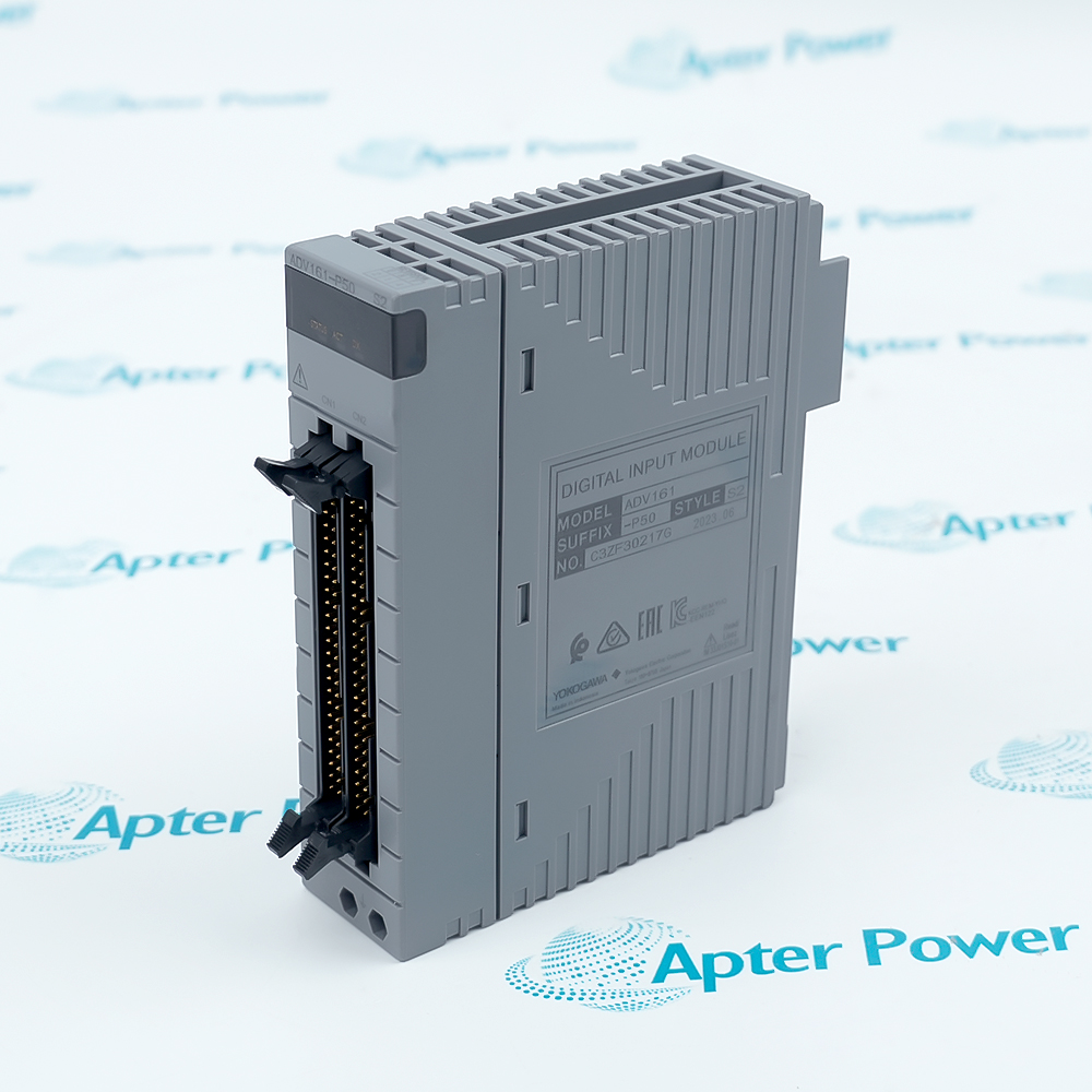
Features:
- Provides 16 non-isolated input channels for standardized transmitter signals.
- Delivers ±16 μA accuracy with 10ms update and 100ms response.
- Supplies 14.8-26.4V at 20mA for 2-wire/4-wire transmitters.
The AAI141-S00 S2 provides 16 non-isolated input channels for receiving 4 to 20 mA DC standardized signals from 2-wire or 4-wire transmitters. Each channel features input resistance ranging from 400 Ω at 20mA to 1000 Ω at 4mA, with input resistance of 500 kΩ or larger when power is OFF. The AAI141-S00 S2 supports setting of 2-wire or 4-wire transmitter for each channel via setting pins, providing flexibility for diverse field device configurations. The module accepts up to 27mA allowable input current and offers withstanding voltage protection, ensuring reliable operation in industrial environments.
The AAI141-S00 S2 delivers exceptional accuracy of ±16 μA, ensuring precise measurement of process signals. The module provides a fast data update period of 10ms and step response time of 100ms, enabling real-time process monitoring and control. The AAI141-S00 S2 features drift due to ambient temperature change of ±16 μA/10°C, maintaining accuracy across varying environmental conditions. The module's fast response and high accuracy make it suitable for demanding applications requiring rapid and precise signal acquisition, such as flow control, pressure monitoring, and temperature regulation.
The AAI141-S00 S2 includes an integrated transmitter power supply providing 14.8V or higher at 20mA and 26.4V or less at 0mA, with output current limit of 27mA. This eliminates the need for external power supplies for 2-wire transmitters, simplifying installation and reducing costs. The AAI141-S00 S2 supports HART communication when installed in ER bus node unit with EB401 firmware revision 2 or later.
The AAI141-S00 S2 YOKOGAWA Analog Input Module may still be available for purchase and support from Apter Power beyond
End-Of-Life (EOL) by the manufacturer (OEM).
YOKOGAWA AAI141-S00 S2 Analog Input Module Manuals,
Datasheets, Drivers, Link
Important Notice: Other accessories, manuals, cables, calibration data, software, etc. are not
included with this equipment unless listed in the above stock item description. All prices are
shown in USD.
YOKOGAWA AAI141-S00 S2 Analog Input Module Specs
General
- Manufacturer YOKOGAWA
- Model AAI141-S00 S2
- Condition New Original ready stock
- Product Family AAI143-H00 S1,AAI143-S00 S1,AAI135-H00 S1,AAI141-H00 S1
Important Notice: Other accessories, manuals, cables, calibration data, software, etc. are not included with this equipment unless listed in the above stock item description. All prices are shown in USD.
- Process Industry Parameter Tracking: Deployed heavily across continuous-process plants (e.g., Oil & Gas, Refining, Petrochemical, and Chemical production) to measure process variables such as flow, pressure, fluid level, and temperature via standard field transmitters.
- Utilities & Energy Infrastructure: Widely utilized in Water & Wastewater processing networks, Boiler Feed-water loops, and Power Generation facilities where 16-channel high-density scanning is required.
- Dual-Redundant Control Loops: Suited for highly critical process loops where module failure cannot be tolerated, as it fully supports dual-redundant hot-swappable mirroring configurations.
- Signal & Channel Architecture: Provides 16 channels optimized specifically for standard 4 to 20 mA DC or 1 to 5 V DC current loop signals. It features onboard channel pins allowing independent configuration for either 2-wire or 4-wire transmitters on a per-channel basis.
- HART Protocol Integration: While the default model processes analog values, the hardware platform supports pass-through digital communication via the HART protocol, allowing the DCS to access advanced field device variables, multi-variable diagnostics, and secondary instrument calibration parameters.
- Pressure Clamp Terminal Blocks: Direct panel termination using models like the ATA4S (single configuration) or ATA4D (dual-redundant configuration).
- S00 Suffix Definition: The "-S" indicates it is a standard performance module, the first "0" specifies no integrated explosion protection (meaning it must be mounted inside a safe-zone control cabinet or inside an explosion-proof purge panel if placed near hazardous environments), and the second "0" indicates the basic, non-modified unit type.
- Physical Isolation Limitations (Non-Isolated): Because it is a Non-Isolated module, channels share a common internal ground. Engineering Note: If the module is used in intrinsically safe (IS) applications extending directly into hazardous zones, it cannot be connected to a simple Zener barrier; instead, an external isolation barrier must be piped into the loop to isolate field faults from the DCS.
- Withstanding Voltage: Capable of insulating up to 500 V AC between the input signal lines and the internal system logic bus when utilizing dedicated Yokogawa KS cables.