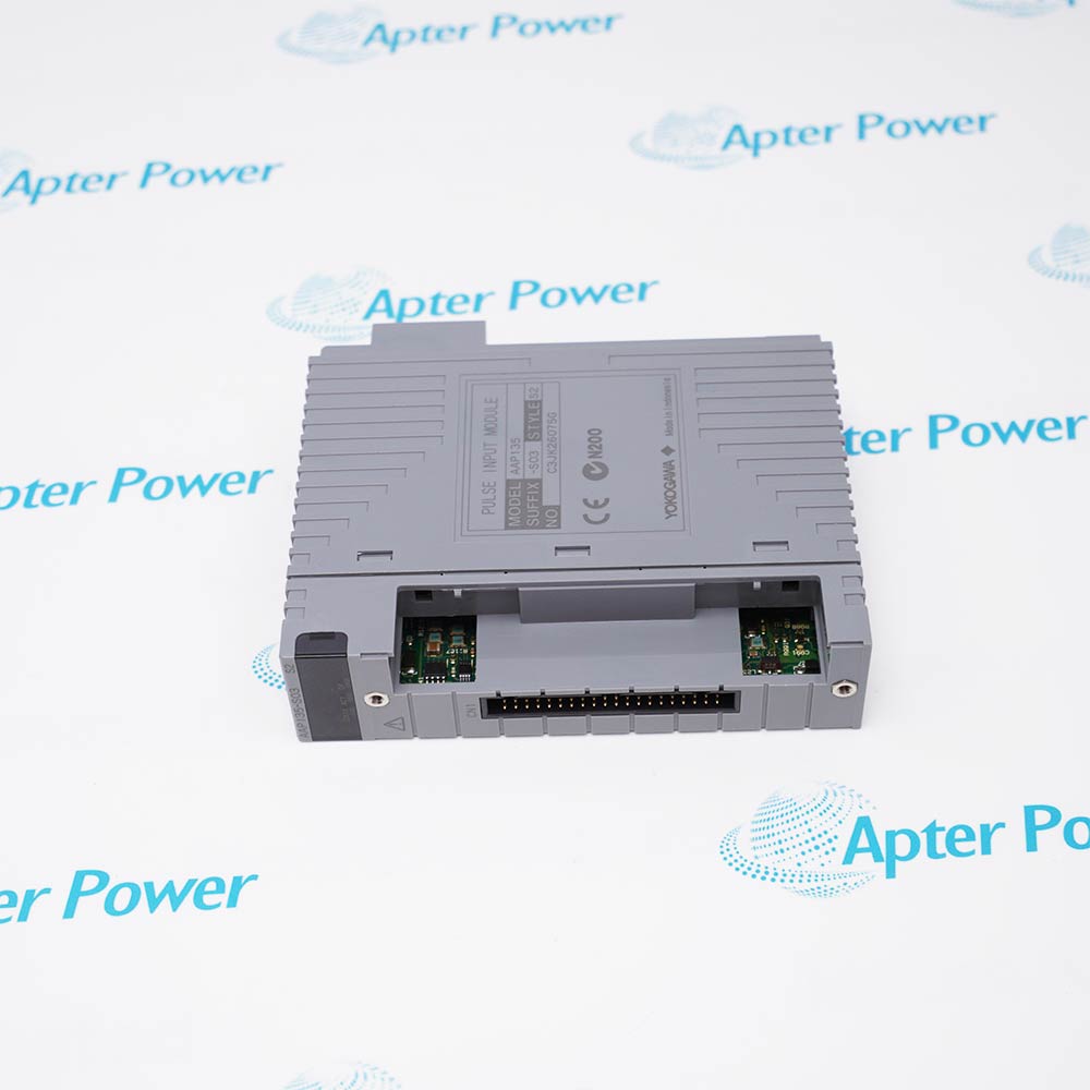
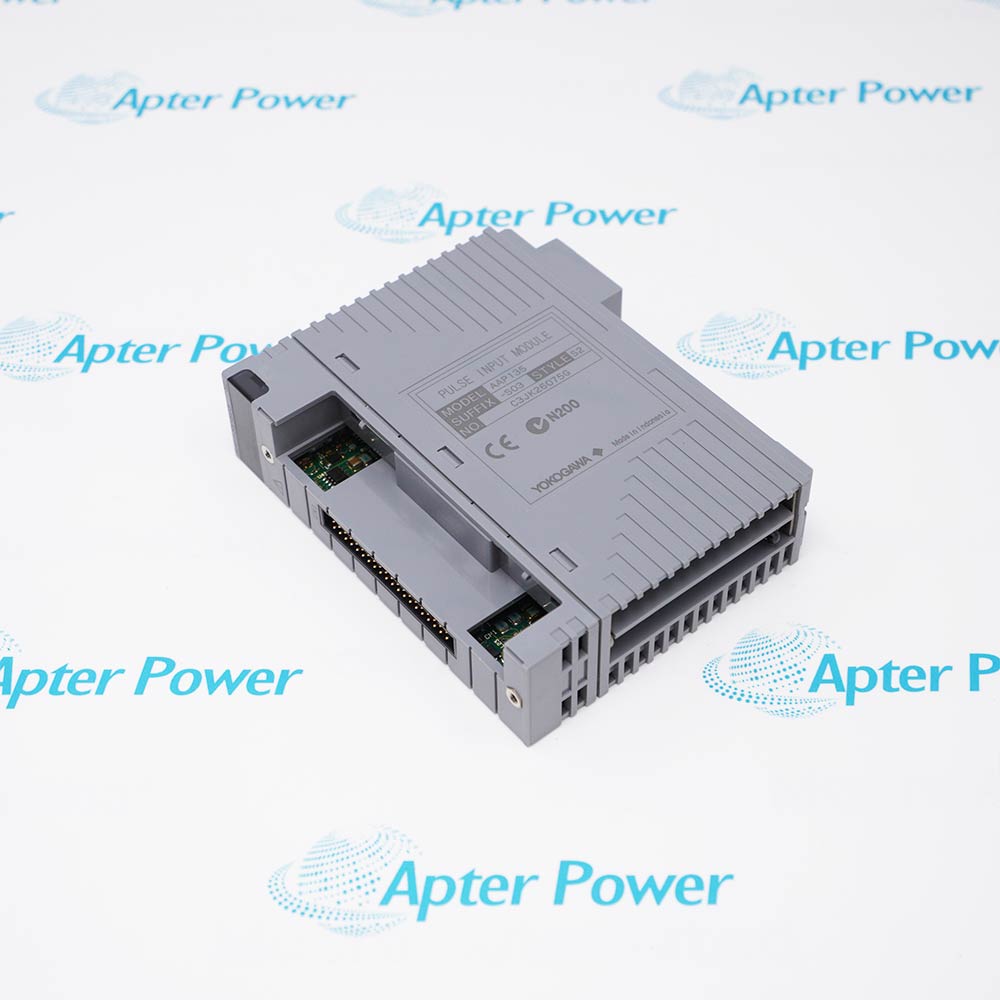
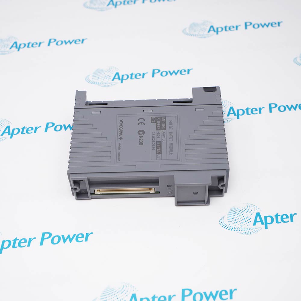
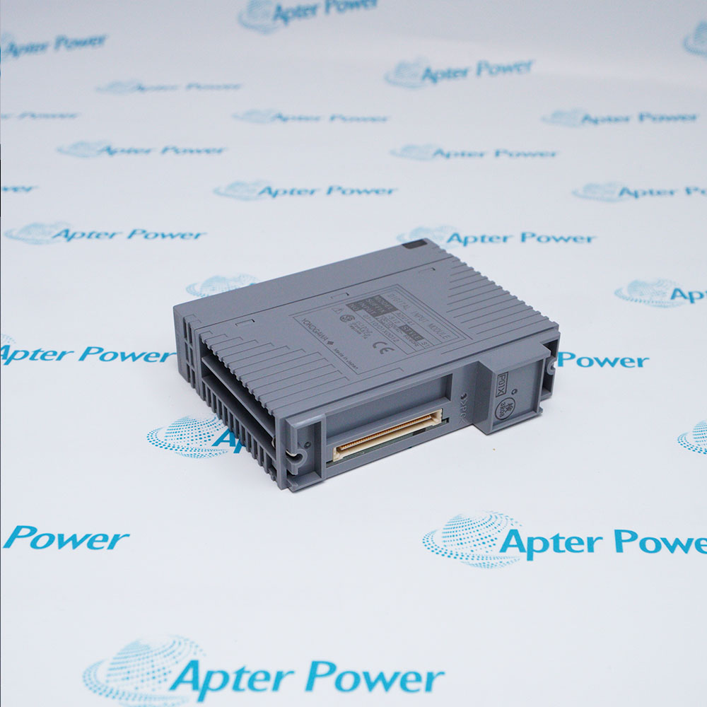
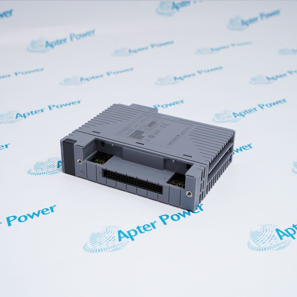
Features:
- Eight pulse-count inputs are isolated channel by channel from the field interface and control system.
- Two-wire contact, voltage and current pulses plus powered three-wire voltage pulses are supported.
- A 2 ms update period and dual-redundant operation support deterministic FCS pulse acquisition.
The AAP135-S03 S2 ordering identity combines the AAP135 pulse-input hardware with the specified S03 configuration and S2 marking.
Within CENTUM VP FIO, the module counts field pulses and transfers updated values to the field control station for use in control and monitoring logic.
Before installation, confirm the terminal option, transmitter supply, signal thresholds, wiring capacitance and single or duplexed module arrangement.
AAP135-S03 S2 availability is confirmed by Apter Power at quotation; match the complete configuration before ordering.
Verified resources for Yokogawa AAP135-S03 S2:
Important Notice: Other accessories, manuals, cables, calibration data, software, etc. are not included with this equipment unless listed in the above stock item description. All prices are shown in USD.
- Counts contact transitions from field devices that provide relay or transistor-contact pulse outputs.
- Acquires voltage-pulse and current-pulse signals for use by CENTUM VP monitoring and control functions.
- Maintains eight independent pulse channels where field-to-system and channel-to-channel isolation are required.
- Supported field control station hardware includes AFV30S, AFV30D, AFV40S and AFV40D.
- Operation is specified with the VP6F1700 Control Function for the supported FCS platforms.
- Engineering is performed with the VP6E5100 Standard Builder Function for the corresponding system release.
- Input circuits withstand 500 V AC for one minute between the field side and the system.
- Adjacent channels are separately isolated and carry the same 500 V AC one-minute withstand rating.
- A configurable low-frequency filter suppresses dry-contact chatter, while the shunt opens on loss of power or on the standby side.
- Field wiring can use a pressure-clamp terminal block, KS cable interface or MIL connector cable arrangement.
- Connection topology must follow the selected contact, voltage-pulse or current-pulse input method and transmitter supply.
- For B-C no-voltage contacts, verify single or duplexed timing limits together with field-device and cable capacitance.