Features:
- Bridge Between Field 4–20 mA Transmitters and CENTUM VP Control Architecture
- Merges 8-Channel Analog Acquisition with Per-Channel Galvanic Isolation
- Functions Alongside FIO-Series I/O Bases and Standard YOKOGAWA Process Controllers
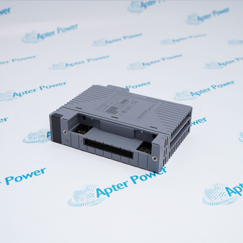
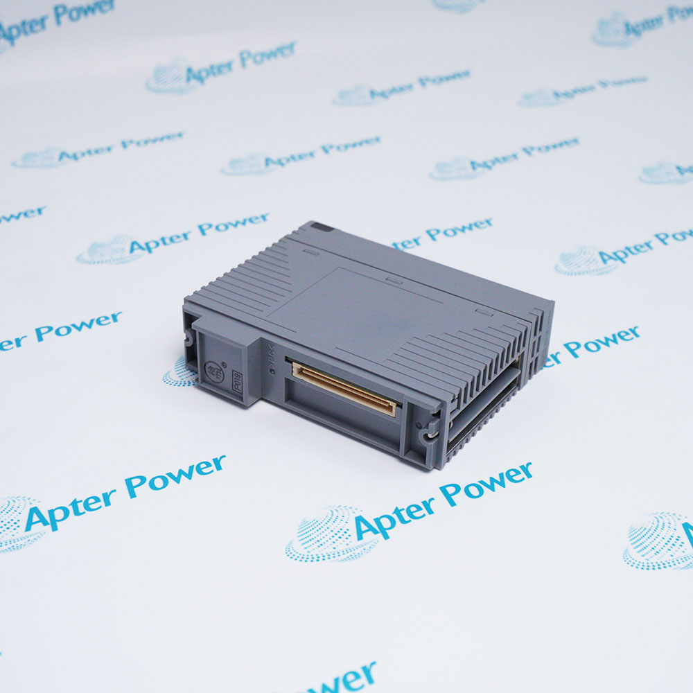
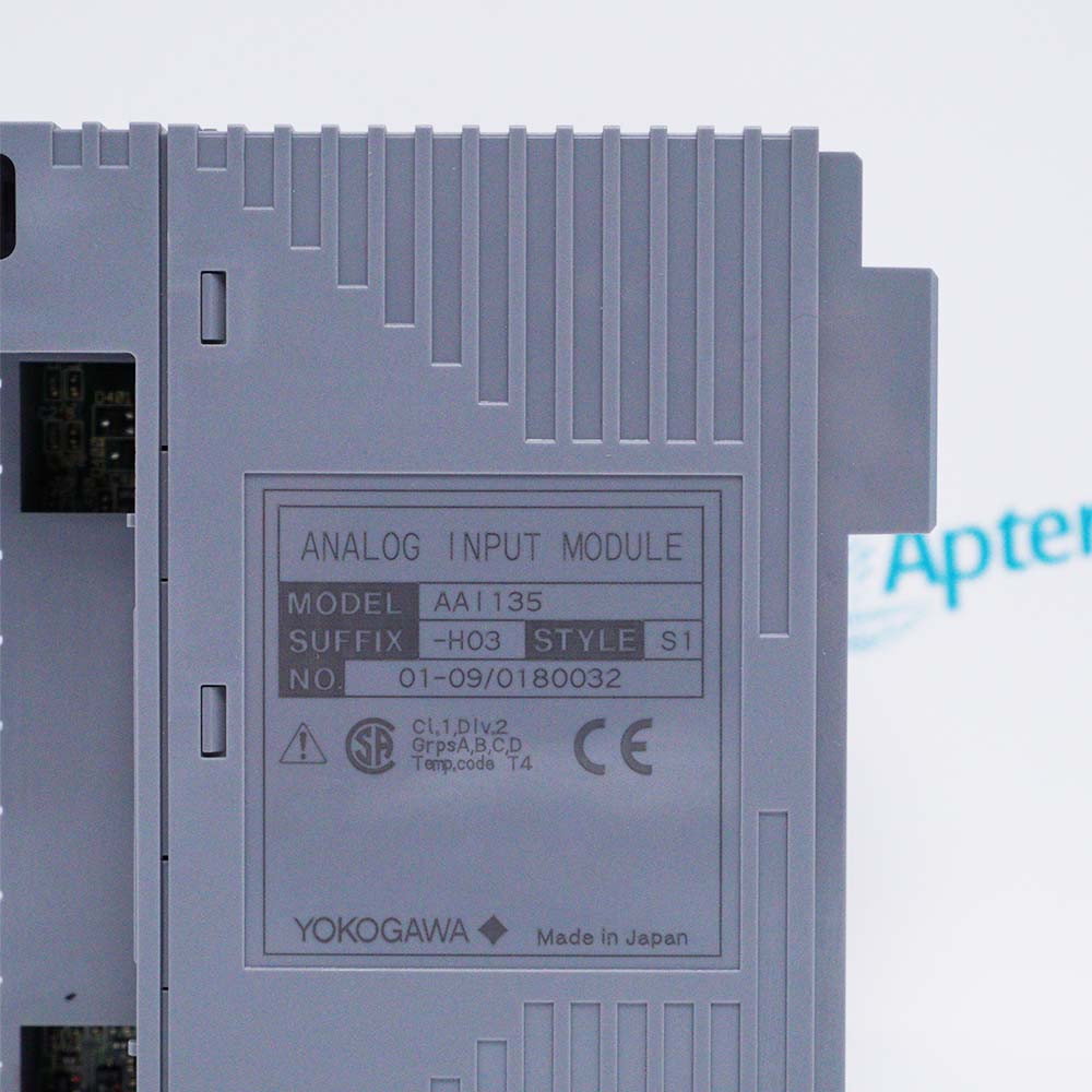
The YOKOGAWA AAI135-H03 S1 Analog Input Module serves as the isolated 4–20 mA input interface in a FIO rack, translating field current-loop signals into digital data for the control system. It continuously accepts eight independent 4–20 mA inputs and converts them through isolated A/D circuitry, forwarding the digitized process values across the rack backplane to the processor module. Native channel-to-channel isolation is built into the AAI135-H03 S1, and because each of the eight inputs is galvanically separated, ground-potential differences between distant field devices cannot create measurement errors or damage downstream electronics. The AAI135-H03 S1 has been refined over earlier analog input designs, adding reinforced isolation barriers and improved common-mode rejection to sustain accuracy in electrically noisy plant environments.
The AAI135-H03 S1 provides essential signal-conditioning functions common to the entire I/O segment, and is a critical component of the measurement path, directly affecting the validity of loop data presented to the operator and control algorithms. One AAI135-H03 S1 module occupies a single slot in the FIO base and can be mixed with other FIO analog or digital modules in the same node. The AAI135-H03 S1 is always recognized by the system configuration tool as an 8-channel isolated AI card, and channel scaling, alarm limits, and fault handling are configured through the standard YOKOGAWA engineering station.
For multi-loop process applications, the AAI135-H03 S1 allows dense packing of analog inputs without external isolators. In addition to straightforward single-module operation, the FIO architecture also permits redundant communication paths; the AAI135-H03 S1 itself feeds its converted data to the dual-redundant bus within the base unit. Using this method, the control system continually validates the integrity of the I/O data. If the primary communication route encounters an anomaly, the AAI135-H03 S1 information is automatically presented through the secondary route, and a diagnostic entry is recorded in the system event log.
The AAI135-H03 S1 YOKOGAWA Analog Input Module may still be available for purchase and support from Apter Power beyond End-Of-Life (EOL) by the manufacturer (OEM).
YOKOGAWA AAI135-H03 S1 Analog Input Module Manuals,Datasheets,Link
Important Notice: Other accessories, manuals, cables, calibration data, software, etc. are not included with this equipment unless listed in the above stock item description. All prices are shown in USD.
YOKOGAWA AAI135-H03 S1 Analog Input Module Specs
General
- Manufacturer YOKOGAWA
- Model AAI135-H03 S1
- Condition New Original ready stock
- Product Family AAI135-H00 S1, AAI135-S00 S2
Important Notice: Other accessories, manuals, cables, calibration data, software, etc. are not included with this equipment unless listed in the above stock item description. All prices are shown in USD.
- Process Monitoring: Collecting real-time data from analog sensors to track variables like pressure, flow, and level.
- Automation Systems: Interfacing with control systems to execute automated tasks based on field measurements.
- Continuous Process Industries: Widely used in sectors such as Oil & Gas, Chemical Processing, Power Generation, and Pharmaceuticals.
- Dual-Redundant Configuration: Can be used in redundant setups to ensure system availability and prevent downtime.
- Certification: The module is CE certified, meeting European safety, health, and environmental protection standards.
- Intrinsic Safety: For intrinsically safe applications, an isolation barrier is required, as a Zener barrier is not permitted for current output with this series.
- Isolation: Features full isolation between the field and the system, as well as between individual channels, providing high noise immunity and protecting the system from electrical faults.
- Operating Temperature: -20°C to +70°C (-4°F to +158°F).
- Storage Temperature: -40°C to +85°C (-40°F to +185°F).
- Relative Humidity: 5% to 95% RH (non-condensing).
- Temperature Rate of Change: Within ±10°C per hour.