Ask our team:
  • Phone: +86 181 0690 9650
  • E-Mail sales1@apterpower.com
  • Lifecycle status

    Active / Available from OEM
    Apter Power reviews voltage maps and paired-common documentation before quoting, condition checking, and dispatch coordination.

IMDSI02

/ 4.9
1001 reviews | Need a Specific Revision?
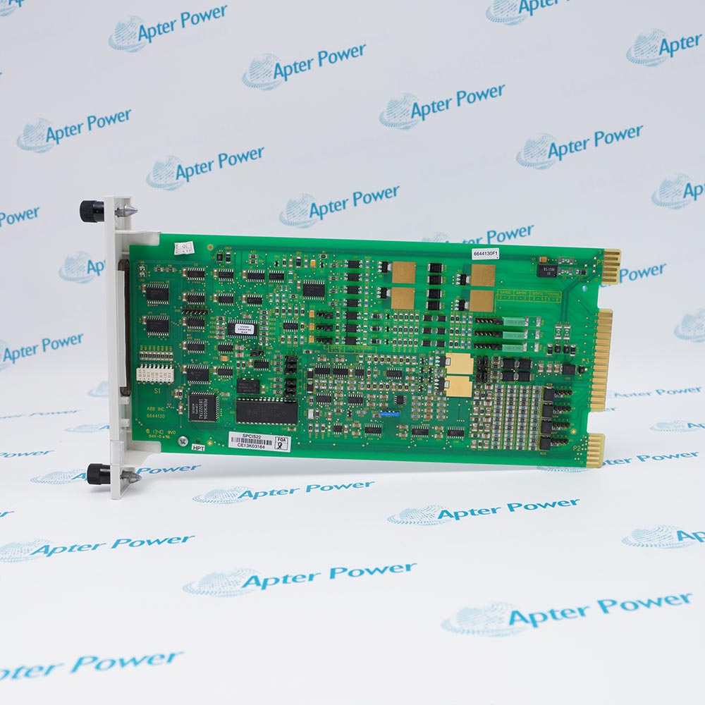
Mixed-voltage digital monitoring is the distinguishing role of ABB IMDSI02, which accepts 24 VDC, 125 VDC, or 120 VAC across sixteen inputs.
In Stock
Ships by Wednesday, October 28
Fast Shipping Available
Get a quick price for IMDSI02
Quantity
*E-mail
Company
*Mobile
*Content
Upload (gif, jpg, jpeg, png, bmp, doc, docx, xls, xlsx, ppt, pdf, csv)

Technical specifications for IMDSI02

  • Manufacturer:
    ABB
  • Part Number:
    IMDSI02
  • Product Family:
    ABB Bailey
  • Product Type:
    Universal Digital Input Module
  • Stock:
    1
  • Digital input channels:
    16
  • Supported DC inputs:
    24 VDC or 125 VDC
  • Supported AC input:
    120 VAC
  • Shared common pair 1:
    Channels 7 and 8
  • Shared common pair 2:
    Channels 15 and 16
  • Paired-common rule:
    Same voltage source within each pair
  • Input isolation:
    Optically isolated
  • Tariff Code:
    Please confirm the destination before shipping
  • Country of origin:
    Sweden
  • Place of shipment:
    Xiamen,Fujian,China
By purchasing this item, you agree to the Terms & Conditions, ApterPower is not an authorized distributor for listed manufacturers or tradenames and therefore the manufacturer's warranty does not apply. All our products come with ApterPower's 1-year warranty.

More Information

Overview Manuals Specifications Voltage Map Shared Commons Mixed-I/O Migration

Features:

  • Sixteen digital inputs supporting three documented voltage classes
  • 24 VDC, 125 VDC, or 120 VAC field service
  • Shared-common restrictions on channel pairs 7-8 and 15-16
IMDSI02 consolidates several discrete field-voltage classes in one Harmony rack input module.

Its paired commons create a real wiring boundary inside an otherwise flexible sixteen-channel arrangement.

Engineering and procurement should treat the voltage schedule and terminal grouping as part of the product configuration.

Availability of IMDSI02 is subject to Apter Power's current inventory and sourcing confirmation.
IMDSI02 Universal Digital Input Module Manuals, Datasheets, Links Important Notice: Other accessories, manuals, cables, calibration data, software, etc. are not included with this equipment unless listed in the above stock item description. All prices are shown in USD.
IMDSI02 Universal Digital Input Module Specs

General

  • ManufacturerABB
  • ModelIMDSI02
  • ConditionNew Original ready stock
  • Product FamilyHarmony Rack I/O
Important Notice: Other accessories, manuals, cables, calibration data, software, etc. are not included with this equipment unless listed in the above stock item description. All prices are shown in USD.

Per-channel source schedule

  • 24 VDC: identify all low-voltage input points.
  • 125 VDC: separate high-voltage DC circuits.
  • 120 VAC: retain AC source and frequency records.
  • Drawing: bind every channel to its approved source.

Paired-channel restriction

  • Channels 7-8: use one common voltage source.
  • Channels 15-16: apply the same-source rule independently.
  • Reassignment: review terminal grouping before moving a point.
  • Isolation: de-energize every affected source during work.

Architecture boundary

  • Inventory: record high- and low-voltage point counts.
  • Segregation: preserve source and common separation.
  • Successor: assume no single-device mapping without official proof.
  • Acceptance: test each voltage class under the approved procedure.
Description
Three documented field-voltage classes give IMDSI02 its universal digital-input role: 24 VDC, 125 VDC, or 120 VAC can be assigned across sixteen Harmony rack input channels according to the approved field design.

Mixed-voltage flexibility has a wiring limit on IMDSI02. Inputs 7 and 8 share one common, and inputs 15 and 16 share another; each paired common must use the same voltage source, so those four channels cannot be reassigned independently without reviewing the terminal plan.

A migration or spare review for IMDSI02 should preserve the per-channel voltage schedule, paired-common grouping, terminal assembly, isolation boundaries, controller addresses, and interlock duties. ABB notes that mixed high- and low-voltage use does not map automatically to one later I/O device.
Alternative Names
IMDSI 02 IMDSI-02 ABB Bailey IMDSI02 Harmony universal digital input module YIMDSI02 mixed-voltage sixteen-channel input card
Technical notes
Map the voltage source before wiring IMDSI02. ABB documents 24 VDC, 125 VDC, and 120 VAC inputs, but channels 7-8 and 15-16 share paired commons and each pair must use the same source. Preserve the voltage schedule, terminal grouping, isolation procedure, and controller references during replacement or migration.
Exceptional Service

Our Mission

  • 100% Satisfaction

    We believe expertise is priceless. With over 20 years of experience, and top engineers on staff, we can help you solve or avoid problems that threaten your business.
  • Trust Guaranteed

    Not only do we have a vast inventory, our team makes sure every piece of equipment is in working condition. Your purchases are also backed by our Warranty.
  • Expertise

    Time is money, especially when your equipment is down. We work quickly to get your equipment on its way so you can get it back up and running.

FAQS

The following is a list of questions commonly asked by our customers. Please contact us if you have a question about our process that is not answered below.
Why must channels 7 and 8 be reviewed together on IMDSI02?
They share a common and must use the same voltage source, so changing one channel can alter the safe wiring conditions of the pair.
How do channels 15 and 16 constrain an IMDSI02 terminal reassignment?
The second paired common follows the same-source rule; verify both circuits and isolate the affected source before moving either conductor.
Can optical isolation alone justify mixing any voltage on IMDSI02?
No. The supported voltage classes and paired-common rules still govern field wiring even though the inputs are optically isolated.
When one IMDSI02 input pair behaves incorrectly, what diagnostic sequence is most useful?
Check the shared source, common continuity, field voltage, terminal assignment, insulation, channel indication, and controller address before replacing hardware.
Why can a mixed high- and low-voltage IMDSI02 application require more than one device during migration?
ABB notes that the mixed-voltage arrangement does not map automatically to one later I/O device, so the point schedule must be engineered by voltage class.
What evidence should accompany an IMDSI02 quotation for a mixed-voltage cabinet?
Provide the exact label, per-channel voltage map, paired-common drawing, termination photographs, controller addresses, quantity, destination, and outage schedule.