Ask our team:
  • Phone: +86 181 0690 9650
  • E-Mail sales1@apterpower.com
  • Lifecycle status

    Active / Available from OEM
    Apter Power checks IPMON01 identity, alarm-interface records, and supplied condition before quotation.

IPMON01

/ 4.9
1001 reviews | Need a Specific Revision?
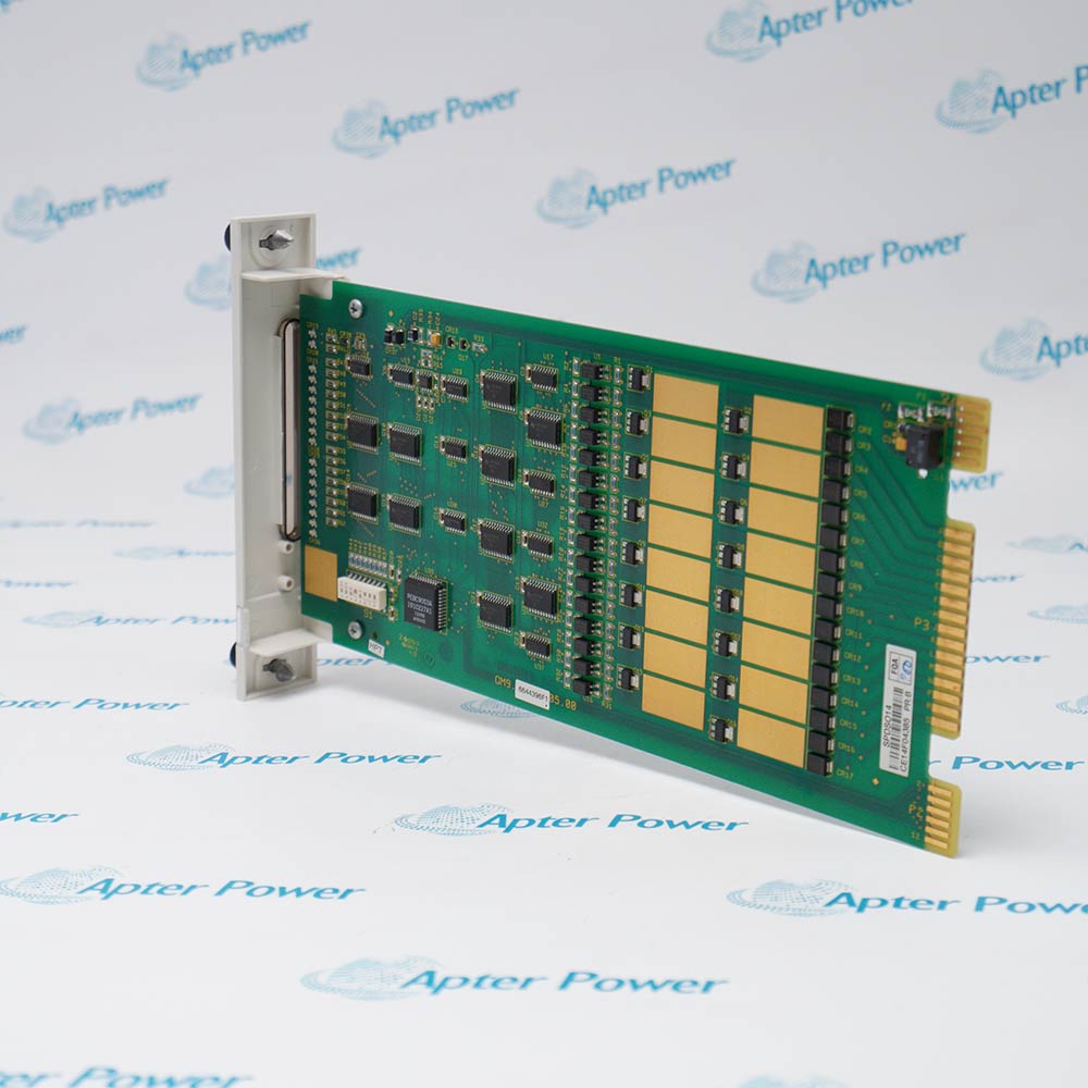
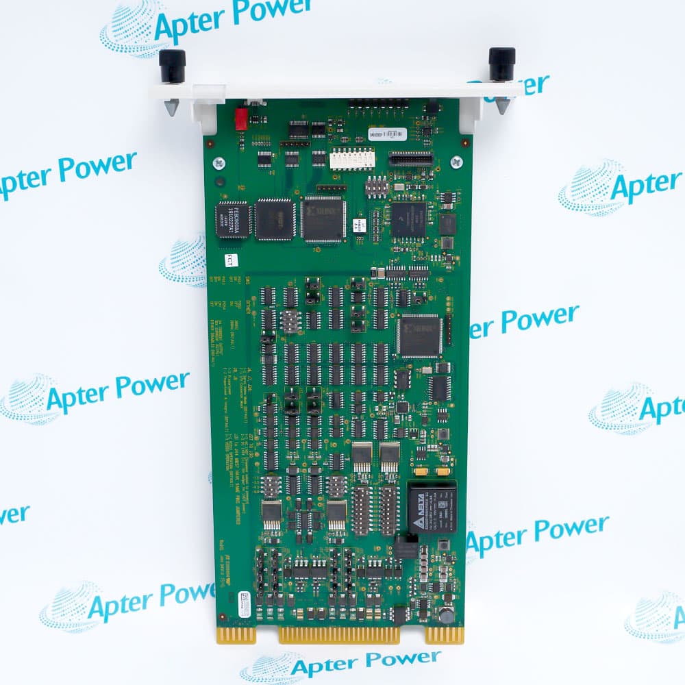
ABB IPMON01 monitors Modular Power System II bus voltages and provides dedicated power and I/O alarm outputs.
In Stock
Ships by Wednesday, October 28
Fast Shipping Available
Get a quick price for IPMON01
Quantity
*E-mail
Company
*Mobile
*Content
Upload (gif, jpg, jpeg, png, bmp, doc, docx, xls, xlsx, ppt, pdf, csv)

Technical specifications for IPMON01

  • Manufacturer:
    ABB
  • Part Number:
    IPMON01
  • Product Family:
    ABB Bailey
  • Product Type:
    Power Monitor Module
  • Stock:
    1
  • Power input:
    0.3 A at 120 VAC; 0.2 A at 240 VAC and 125 VDC
  • Monitored system buses:
    5 VDC, +15 VDC, -15 VDC, 25.5 VDC, 49.1 VDC auxiliary, 125.6 VDC auxiliary
  • Alarm outputs:
    Power alarm and I/O alarm; opto-isolated open collector, 24 V
  • Logic 0 output:
    ≤1.2 VDC at 150 mA sink current
  • Logic 1 output:
    ≥5 to 30 VDC at 80 µA source current
  • Weight:
    0.71 kg
  • Estimated shipping dimensions:
    21.84x3.56x40.13cm
  • Tariff Code:
    Please confirm the destination before shipping
  • Country of origin:
    Sweden
  • Place of shipment:
    Xiamen,Fujian,China
By purchasing this item, you agree to the Terms & Conditions, ApterPower is not an authorized distributor for listed manufacturers or tradenames and therefore the manufacturer's warranty does not apply. All our products come with ApterPower's 1-year warranty.

More Information

Overview Manuals Specifications Bus Monitor Alarms Service

Features:

  • Supervision of defined MPSII system-bus voltages
  • Separate opto-isolated power and I/O alarm outputs
  • Published low- and high-trip windows for monitored buses
IPMON01 provides the cabinet-level monitoring function within ABB Modular Power System II.

The module compares system buses with documented trip windows and reports faults through dedicated alarm channels.

Troubleshooting should distinguish the monitored bus condition from the alarm-output circuit and the monitor hardware itself.

Availability of IPMON01 is subject to Apter Power's current inventory and sourcing confirmation.
IPMON01 Manuals, Datasheets, Links Important Notice: Other accessories, manuals, cables, calibration data, software, etc. are not included with this equipment unless listed in the above stock item description. All prices are shown in USD.
ABB IPMON01 Power Monitor Module Specs

General

  • ManufacturerABB
  • ModelIPMON01
  • ConditionNew Original ready stock
  • Product FamilyABB Bailey
Important Notice: Other accessories, manuals, cables, calibration data, software, etc. are not included with this equipment unless listed in the above stock item description. All prices are shown in USD.

Monitored-voltage logic

  • Bus set: use the exact MPSII voltages listed by ABB
  • Trip windows: compare readings with the published low and high points
  • Auxiliary buses: identify 25.5, 49.1, and 125.6 V paths correctly
  • Diagnosis: trace the source bus before condemning the monitor

Status-interface planning

  • Power alarm: route the dedicated power-fault output
  • I/O alarm: keep I/O status separate from power status
  • Output type: observe the opto-isolated open-collector interface
  • Site logic: match polarity and alarm handling to the approved design

Maintenance sequence

  • Chassis: confirm the installed MPSII power-module chassis
  • Baseline: record normal bus values before intervention
  • Replacement: follow the documented online-service procedure where applicable
  • Validation: test both alarm channels after restoration
Description
IPMON01 is the power monitor module for ABB's Modular Power System II. It supervises the documented system buses and exposes separate power-alarm and I/O-alarm outputs for cabinet status handling.

ABB specifies IPMON01 input current at 0.3 A from 120 VAC and 0.2 A from 240 VAC or 125 VDC. Its monitor thresholds cover the 5 V, positive and negative 15 V, 25.5 V, auxiliary 49.1 V, and auxiliary 125.6 V buses defined in the data sheet.

When applying IPMON01, confirm the installed MPSII chassis, monitored bus set, alarm wiring, and site response logic. Alarm interpretation should separate a monitored power condition from an I/O alarm before module replacement.
Alternative Names
ABB IPMON01 IPMON 01 IPMON-01 ABB Bailey IPMON01 MPS II IPMON01
Technical notes
Map the alarm circuits before replacing IPMON01: ABB provides separate opto-isolated power and I/O alarm outputs, each driven at 24 V, and publishes bus-specific trip thresholds. Confirm the MPSII chassis, monitored voltage set, output polarity, and site alarm logic so a downstream fault is not mistaken for monitor-module failure.
Exceptional Service

Our Mission

  • 100% Satisfaction

    We believe expertise is priceless. With over 20 years of experience, and top engineers on staff, we can help you solve or avoid problems that threaten your business.
  • Trust Guaranteed

    Not only do we have a vast inventory, our team makes sure every piece of equipment is in working condition. Your purchases are also backed by our Warranty.
  • Expertise

    Time is money, especially when your equipment is down. We work quickly to get your equipment on its way so you can get it back up and running.

FAQS

The following is a list of questions commonly asked by our customers. Please contact us if you have a question about our process that is not answered below.
When IPMON01 reports a low-bus condition, how should its published trip window guide diagnosis?
Measure the affected bus and compare the reading with ABB's minimum and maximum low-trip limits before attributing the condition to the monitor hardware.
Why can IPMON01 indicate an I/O fault while its monitored voltage buses remain within range?
The module maintains a separate I/O alarm path, so an I/O-status condition can remain active independently of the power-bus trip logic.
Which IPMON01 interfaces require polarity-aware logic at the cabinet alarm destination?
The documented 24 V opto-isolated open-collector power and I/O alarm outputs must be matched to the approved sink/source logic and destination wiring.
How can the fan-status inputs on IPMON01 narrow an overheating investigation?
ABB provides two low-fan-speed inputs associated with temperature-controlled fan operation; compare those states with cabinet temperature and airflow before replacing the monitor.
What evidence separates input-source sag from a system-bus fault observed through IPMON01?
Compare the applicable 120 VAC, 240 VAC, or 125 VDC input trip point with the individual system-bus trip table and the measured source voltage.
When should radio-frequency exposure near IPMON01 stop a commissioning test?
ABB warns against RFI sources producing 10 V/m or more at 84.9 MHz within 2.2 m of the Modular Power System II.
Which baseline records make a later IPMON01 alarm investigation reproducible?
Archive normal input voltage, monitored-bus readings, fan-status states, alarm-output logic, cabinet temperature, and the drawing revision used during acceptance.

Product Browsing History