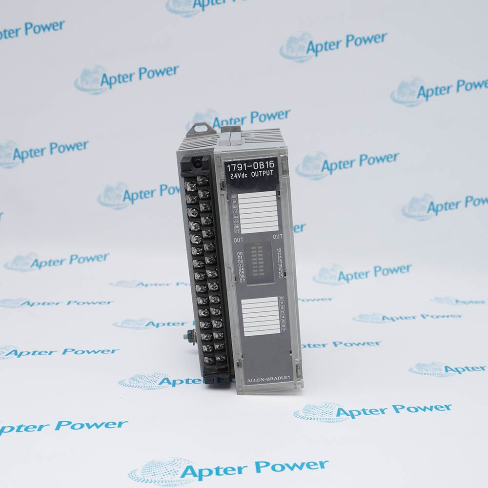
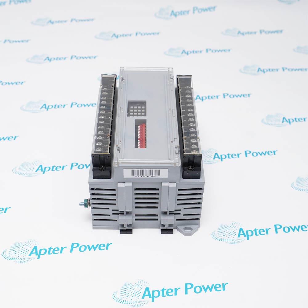
Ask our team:
  • Phone: +86 181 0690 9650
  • E-Mail sales1@apterpower.com
  • Lifecycle status

    Discontinued / Obsolete by OEM
    Apter Power supports 1791-N4V2 quotations, manuals, revision checking, and exact-model matching.

1791-N4V2

/ 4.9
1001 reviews | Need a Specific Revision?
Allen-Bradley 1791-N4V2 is an analog Block I/O module that acquires four selectable voltage or current inputs and sends two voltage commands over a Remote I/O link.
In Stock
Ships by Wednesday, October 28
Fast Shipping Available
Get a quick price for 1791-N4V2
Quantity
*E-mail
Company
*Mobile
*Content
Upload (gif, jpg, jpeg, png, bmp, doc, docx, xls, xlsx, ppt, pdf, csv)

Technical specifications for 1791-N4V2

  • Manufacturer:
    Allen-Bradley
  • Part Number:
    1791-N4V2
  • Product Family:
    1791 Block I/O
  • Product Type:
    4-Input / 2-Output Analog Block I/O Module
  • Stock:
    1
  • Analog Inputs:
    4
  • Analog Outputs:
    2 voltage outputs
  • Input Signal Ranges:
    ±10 V, ±5 V, 0–10 V, 0–5 V, ±20 mA and 0–20 mA
  • Output Signal Range:
    ±10 V
  • Converter Resolution:
    14 bit
  • Communication Network:
    Allen-Bradley Remote I/O
  • External Power:
    85 to 132 V AC
  • Supply Frequency:
    47 to 63 Hz
  • Maximum Supply Current:
    150 mA at 132 V AC
  • Input Update Time:
    25 ms maximum
  • Output Update Time:
    25 ms maximum
  • Terminal Type:
    Removable terminal strip
  • Communication Rates:
    57.6, 115.2 or 230.4 kbit/s
  • Operating Temperature:
    0 to 60 °C
  • Storage Temperature:
    -40 to +85 °C
  • Recommended Mounting:
    Vertical; horizontal permitted with derating guidance
  • Resolution:
    14 bit full scale
  • Input Ranges:
    ±10 V, ±5 V, 0–10 V, 0–5 V, ±20 mA, or 0–20 mA
  • Input Update:
    108 ms per channel
  • Input Impedance:
    10 MΩ voltage; 249 Ω current
  • Estimated shipping dimensions:
    17.65x6.88x9.8cm
  • Tariff Code:
    85389091
  • Country of origin:
    USA
  • Place of shipment:
    Xiamen,Fujian,China
By purchasing this item, you agree to the Terms & Conditions, ApterPower is not an authorized distributor for listed manufacturers or tradenames and therefore the manufacturer's warranty does not apply. All our products come with ApterPower's 1-year warranty.

More Information

Overview Manuals Input Wiring Remote I/O Setup Output Paths Link Diagnostics

Features:

  • Four inputs accept selectable voltage or current ranges with 14-bit conversion.
  • Two ±10 V outputs update independently and include continuous short-circuit protection.
  • The integral Remote I/O adapter uses switch-set addressing, transfer behavior, and link rate.
Allen-Bradley 1791-N4V2 combines analog acquisition, analog command, AC module power, and Remote I/O communication in one block.

Input wiring on 1791-N4V2 changes with voltage, customer-powered current, or block-powered current operation, while each channel retains its assigned return path.

Scanner configuration, switch settings, cable termination, and the 1791-N4V2 status indicators work together when diagnosing missing analog data.

The Allen-Bradley 1791-N4V2 Analog Block I/O Module may still be available for purchase and support from Apter Power beyond End-Of-Life (EOL) by the manufacturer (OEM).
Allen-Bradley 1791-N4V2 Block I/O Analog Module Manuals,Datasheets,Link Important Notice: Other accessories, manuals, cables, calibration data, software, etc. are not included with this equipment unless listed in the above stock item description. All prices are shown in USD.

Selectable Analog Input Circuits

  • Voltage path: Each channel provides a voltage input, return, and ground terminal for its configured range.
  • Current path: Current signals enter through the current-input terminal and use the same channel return organization.
  • Loop supply: A transmitter can use customer-supplied loop power or the module's 24 V DC terminal-25 source.
  • Shunt limit: The 249 Ω current shunt is rated at 0.25 W, so loop conditions must remain within that boundary.

Switch and Scanner Coordination

  • Rack address: SW1 assigns the Remote I/O rack number that the scanner uses to locate the block.
  • Starting quarter: The first two SW1 positions select module groups 0, 2, 4, or 6 within the chosen rack.
  • Transfer behavior: SW2 selects block or discrete transfer together with processor restart or lockout and output hold behavior.
  • Communication rate: The 57.6, 115.2, or 230.4 kbit/s switch setting must match the scanner and every device on the link.

Two Voltage Command Channels

  • Command conversion: The digital output word is converted into a 14-bit analog voltage for each of the two channels.
  • Load requirement: Each ±10 V output must drive a load of 1 kΩ or greater to remain within the documented compliance.
  • Update interval: Each output channel refreshes in 10 ms, independently of the 108 ms input-channel conversion.
  • Fault tolerance: Indefinite short-circuit protection limits damage from a sustained output wiring fault.

Indicators and End Termination

  • POWER indication: The POWER indicator confirms that the module's AC supply is present.
  • COMM indication: Steady COMM shows an established Remote I/O exchange, while flashing reflects reset commands in program mode.
  • FAULT indication: A lit or flashing FAULT state identifies module, low-power, cable, timing, or communication-loss conditions.
  • End resistor: The final block uses 150 Ω at 57.6 or 115.2 kbit/s and 82 Ω at 230.4 kbit/s across BLU and CLR.
Description
Allen-Bradley 1791-N4V2 is a 1791 Block I/O combination analog module that places four configurable input channels and two voltage output channels on an Allen-Bradley Remote I/O link. The scanner transfers analog words to and from the block while the module performs the field-side conversion.

At each input of 1791-N4V2, the range switch determines whether the terminal accepts the documented bipolar or unipolar voltage span or a current-loop signal. The converter represents that electrical level in the block-transfer read data, keeping input scaling separate from the two commanded output words.

Address switches on 1791-N4V2 set the rack number, starting group and communication rate used by the Remote I/O scanner. Transfer, hold-last-state and lockout selections define how the block exchanges data and how the outputs react when normal communication is interrupted.

Field power for 1791-N4V2 enters through the AC supply terminals, while analog conductors land on the removable strip. The preferred vertical position preserves the documented ventilation path, and separation from high-energy wiring reduces interference before the signals reach the converter.
Revisions

Revision Part #

Also known as

1791-N4V2 Series A
1791-N4V2/A, Series A, Rev A
Alternative Names
1791N4V2 1791 N4V2 Allen-Bradley 1791-N4V2 Allen Bradley 1791-N4V2 A-B 1791-N4V2 1791 Block I/O 1791-N4V2 1791-N4V-2 I791-N4V2
Technical notes
Allen-Bradley 1791-N4V2 uses input-range switches and block-transfer data to exchange four analog inputs and two voltage outputs with a Remote I/O scanner. Match the rack address, starting group, baud rate and transfer options before reconnecting field wiring.
Exceptional Service

Our Mission

  • 100% Satisfaction

    We believe expertise is priceless. With over 20 years of experience, and top engineers on staff, we can help you solve or avoid problems that threaten your business.
  • Trust Guaranteed

    Not only do we have a vast inventory, our team makes sure every piece of equipment is in working condition. Your purchases are also backed by our Warranty.
  • Expertise

    Time is money, especially when your equipment is down. We work quickly to get your equipment on its way so you can get it back up and running.

FAQS

The following is a list of questions commonly asked by our customers. Please contact us if you have a question about our process that is not answered below.
Why does 1791-N4V2 return the wrong engineering value for an input?
Check the 1791-N4V2 input-range switch matches the field signal and that the controller applies the corresponding numeric scaling.
Can 1791-N4V2 accept both current and voltage transmitters?
Yes. The four 1791-N4V2 inputs support the documented voltage and current ranges when each channel is wired and selected correctly.
What must match before 1791-N4V2 appears on Remote I/O?
Set the 1791-N4V2 rack number, starting group and communication rate to the assignments used by the Remote I/O scanner.
How should 1791-N4V2 outputs behave after a communication loss?
The 1791-N4V2 hold-last-state and related transfer settings determine the documented output reaction, so record those switches before replacement.
Is horizontal mounting allowed for 1791-N4V2?
The 1791-N4V2 instructions permit horizontal mounting, but vertical mounting is recommended and the stated thermal guidance must be observed.