Features:
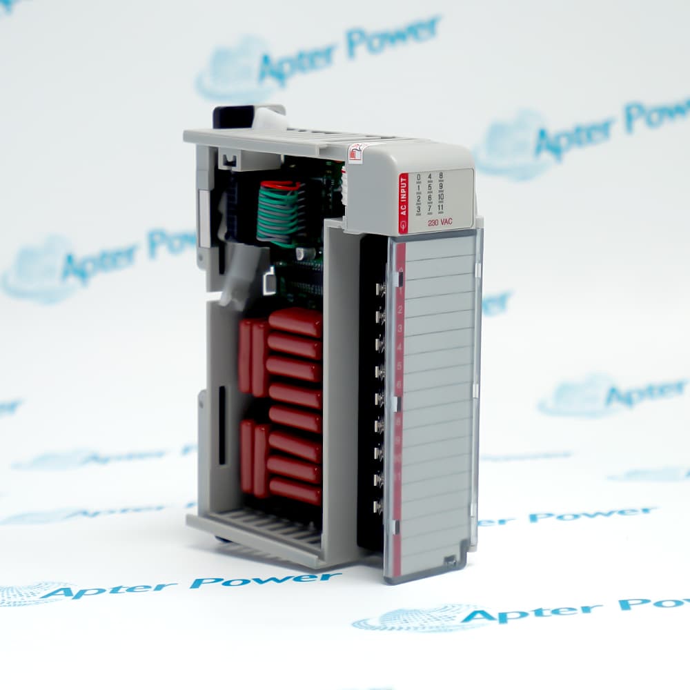
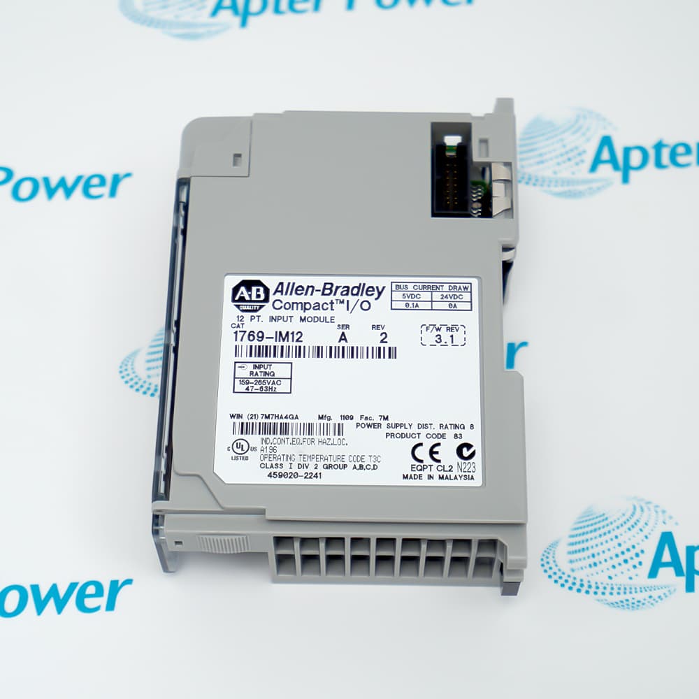
- Allen-Bradley 1769-IM12 receives twelve 200/240 V AC field states through one input group.
- Both input transitions use a documented 20 ms delay before the controller image changes.
- Panel and DIN-rail installation are supported within the eight-position distance rating.
The internally connected commons keep all twelve points in one field group rather than splitting them into isolated banks.
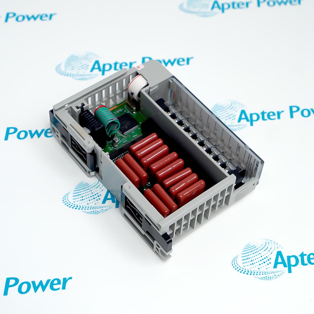
The removable terminal block carries the AC field conductors while the side bus transfers the resulting input states to the controller.
Isolation separates the field circuits from the Compact I/O bus, and the bus connector must be locked between adjoining modules.
The Allen-Bradley 1769-IM12 12-Point 200/240 V AC Digital Input Module may still be available for purchase and support from Apter Power beyond End-Of-Life (EOL) by the manufacturer (OEM).
Allen-Bradley 1769-IM12 12-Point 200/240 V AC Digital Input Module Manuals,Datasheets,Link
Important Notice: Other accessories, manuals, cables, calibration data, software, etc. are not included with this equipment unless listed in the above stock item description. All prices are shown in USD.
How the twelve AC points share one field reference
- Single bank: Inputs 0 through 11 belong to one documented group.
- Common path: The common terminals are internally connected inside the module.
- Field source: Each point changes state from an AC signal referenced to that shared common arrangement.
- Controller image: The side bus reports all twelve point states after the input delay.
Conditions that define a valid input state
- Voltage window: The field signal must remain inside the documented 159–265 V AC operating range.
- Frequency window: The input circuits are specified for 47–63 Hz AC sources.
- ON threshold: A valid ON state requires the stated minimum voltage and current at the terminal.
- OFF boundary: Leakage must stay below the maximum off-state voltage and current limits.
Placing the module in a Compact I/O assembly
- Distance rating: The module can occupy a position no more than eight slots from the power source.
- Side connection: Its bus lever closes the electrical and mechanical link to the adjacent module.
- Logic supply: The 1769 bus provides the module electronics with 5.1 V DC current.
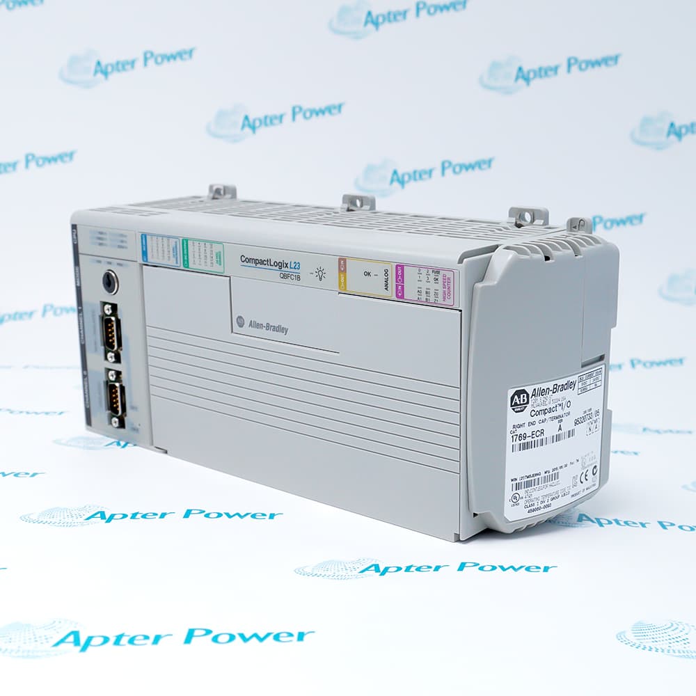
- End position: A properly installed end cap terminates the final bus connection.
Preparing the removable field-wiring block
- Wire range: The screw terminals accept the documented solid or stranded copper conductor sizes.
- Terminal torque: Field screws use the specified tightening torque to secure the conductors.
- Retention: The block retaining screws use a separate lower torque value.
- De-energized work: Field and bus power must be removed before inserting or removing the module or terminal block.