Ask our team:
  • Phone: +86 181 0690 9650
  • E-Mail sales1@apterpower.com
  • Lifecycle status

    Discontinued

1757-SRM

/ 4.9
1001 reviews | Need a Specific Revision?
Allen-Bradley 1757-SRM is a system redundancy module that synchronizes paired ProcessLogix or ControlLogix chassis for controller switchover.
In Stock
Ships by Wednesday, October 28
Fast Shipping Available
Get a quick price for 1757-SRM
Quantity
*E-mail
Company
*Mobile
*Content
Upload (gif, jpg, jpeg, png, bmp, doc, docx, xls, xlsx, ppt, pdf, csv)

Technical specifications for 1757-SRM

  • Manufacturer:
    Allen-Bradley
  • Part Number:
    1757-SRM
  • Product Family:
    ControlLogix
  • Product Type:
    ProcessLogix and ControlLogix System Redundancy Module
  • Stock:
    1
  • Backplane Current at 3.3 V DC:
    0.75 A
  • Backplane Current at 5.1 V DC:
    1.0 A
  • Backplane Current at 24 V DC:
    0.160 A
  • Power Dissipation:
    11.28 W maximum
  • Thermal Dissipation:
    38.49 BTU/h maximum
  • Mounting:
    ControlLogix chassis
  • Enclosure Type Rating:
    None; open-style
  • Fiber Connector:
    SC
  • Fiber Type:
    62.5/125 µm multimode
  • Optical Wavelength:
    1300 nm
  • Fiber Channels:
    One transmit and one receive
  • Relay Supply:
    11 to 30 V DC, 270 mA typical at 24 V DC
  • Pilot Duty:
    30 V DC Class 2 or SELV, 100 mA
  • Wire Size:
    22 to 14 AWG solid or stranded copper
  • Terminal Torque:
    0.6 to 0.8 N·m
  • Operating Temperature:
    0°C to 60°C
  • Storage Temperature:
    -40°C to 85°C
  • Relative Humidity:
    5% to 95%, non-condensing
  • Operating Shock:
    30 g
  • Nonoperating Shock:
    50 g
  • Dimensions:
    7.0 × 14.5 × 14.0 cm
  • Weight:
    0.452 kg
  • Tariff Code:
    8538900000
  • Country of origin:
    USA
  • Place of shipment:
    Xiamen, Fujian, China
By purchasing this item, you agree to the Terms & Conditions, ApterPower is not an authorized distributor for listed manufacturers or tradenames and therefore the manufacturer's warranty does not apply. All our products come with ApterPower's 1-year warranty.

More Information

Overview Manuals Redundancy Fiber Link Status Relay Application
  • Synchronizes a matched pair of redundant control chassis
  • Supports ProcessLogix and ControlLogix redundancy systems
  • Uses a dedicated multimode fiber link between redundancy modules

1757-SRM is an Allen-Bradley system redundancy module designed for paired ProcessLogix and ControlLogix chassis.

The module exchanges synchronization data with its partner, manages primary and secondary redundancy states, and provides relay contacts for external system-status indication.

Before installation or replacement, verify module series, qualified firmware, identical chassis contents, fiber cable, relay wiring, grounding, and the saved redundancy configuration.

Availability, condition, price, and shipping time for 1757-SRM are confirmed during quotation.

Allen-Bradley 1757-SRM ProcessLogix and ControlLogix System Redundancy Module Manuals, Datasheets, Links

Important Notice: Other accessories, manuals, cables, calibration data, software, etc. are not included with this equipment unless listed in the above stock item description. All prices are shown in USD.

  • One module is installed in each chassis of the redundant pair
  • The chassis powered first assumes the primary role during startup
  • Both modules and controllers must qualify before redundant operation
  • The redundancy link uses SC optical connectors
  • The specified cable is 62.5/125 µm multimode fiber
  • One transmit and one receive channel operate at 1300 nm
  • Series B provides normally open, normally closed, and common relay terminals
  • The relay circuit uses an external 11 to 30 V DC supply
  • Shielding and grounding must follow the official wiring diagram
  • ProcessLogix redundant controller systems
  • ControlLogix redundant controller systems
  • High-availability control systems using synchronized primary and secondary chassis
Description
1757-SRM is an Allen-Bradley system redundancy module for ProcessLogix and ControlLogix redundant control platforms.

A matched pair exchanges synchronization data over a 1300 nm multimode fiber link and provides relay contacts for redundancy-system status indication.

Before installation or replacement, confirm the complete catalog number, module series, qualified firmware, identical chassis hardware, fiber cable, relay wiring, grounding, and the saved redundant-system configuration.
Revisions

Revision Part #

Also known as

1757-SRM Ser A
1757-SRM/A, Series A, Rev A
1757-SRM Ser B
1757-SRM/B, Series B, Rev B
Alternative Names
1757-SRM Allen-Bradley 1757-SRM Rockwell Automation 1757-SRM AB 1757-SRM A-B 1757-SRM ProcessLogix 1757-SRM ControlLogix 1757-SRM
Technical notes
1757-SRM installation or replacement requires matching the module series, controller firmware, paired chassis hardware, approved fiber cable, relay wiring, and saved redundancy configuration; incompatibility can prevent synchronization or automatic switchover.
Exceptional Service

Our Mission

  • 100% Satisfaction

    We believe expertise is priceless. With over 20 years of experience, and top engineers on staff, we can help you solve or avoid problems that threaten your business.
  • Trust Guaranteed

    Not only do we have a vast inventory, our team makes sure every piece of equipment is in working condition. Your purchases are also backed by our Warranty.
  • Expertise

    Time is money, especially when your equipment is down. We work quickly to get your equipment on its way so you can get it back up and running.

FAQS

The following is a list of questions commonly asked by our customers. Please contact us if you have a question about our process that is not answered below.
Does 1757-SRM require a second identical module for redundancy?
Yes. The redundant system uses one 1757-SRM in each matched chassis, connected by the approved fiber cable and operated with compatible controller and module firmware.
Can Series A and Series B versions of 1757-SRM be mixed?
Do not assume interchangeability. Verify the exact series, firmware qualification, controller pair, chassis hardware, and redundancy release requirements before combining or replacing modules.
Which cable should be ordered with 1757-SRM?
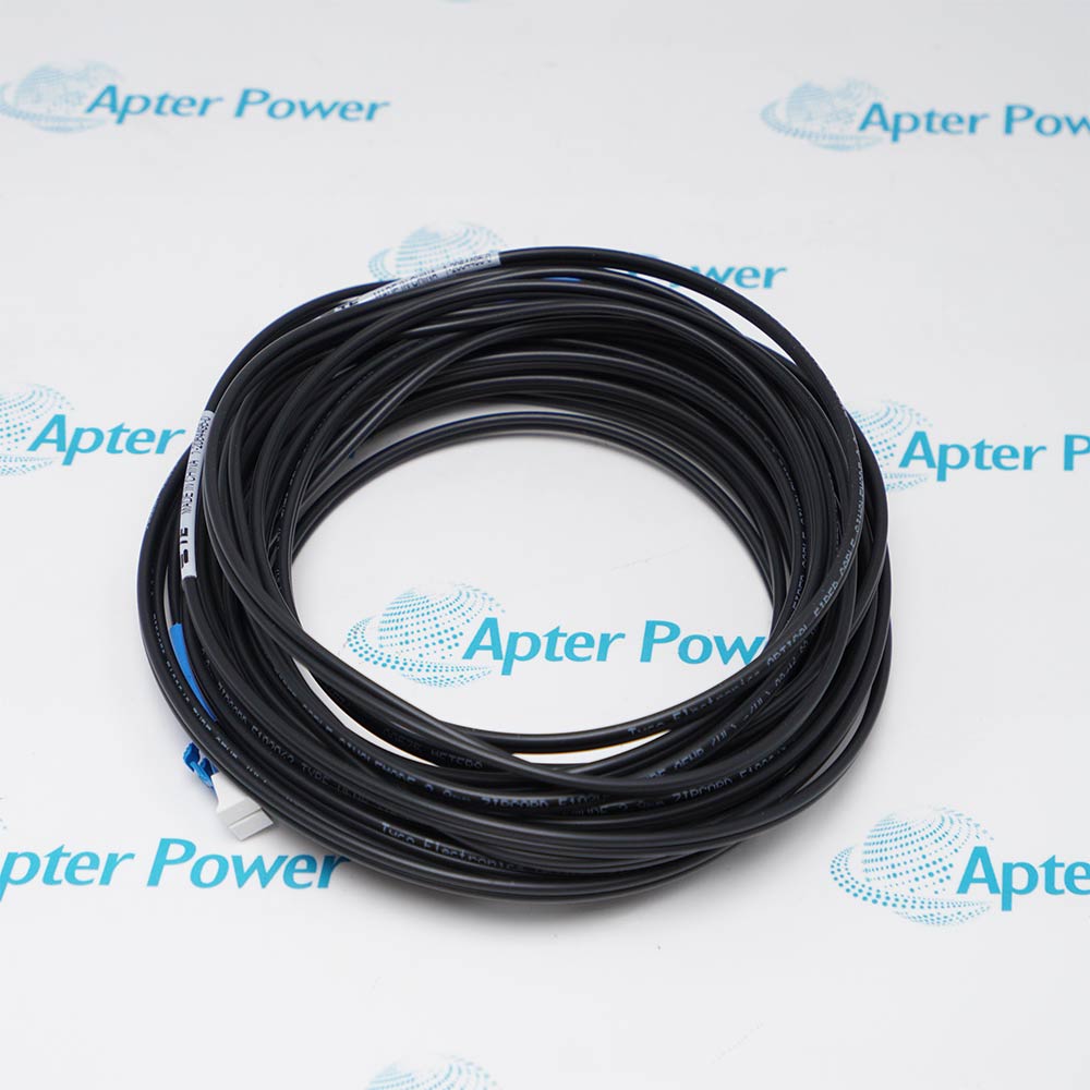
Use a 1757-SRC-series redundancy cable whose documented length fits the chassis separation; the module optical interface uses SC connections with 62.5/125 µm multimode fiber.
Can 1757-SRM be installed or removed while power is applied?
Series B instructions permit insertion or removal under power in applicable nonhazardous conditions, but hazardous-location warnings and the site-approved procedure must be followed.
What must match before commissioning a replacement 1757-SRM?
Confirm identical redundant-chassis hardware, qualified firmware, correct fiber routing, relay wiring, controller configuration, and that the intended primary and secondary modules fully qualify.
What do the relay contacts on 1757-SRM provide?
They provide external status signaling for the redundancy module through the documented normally open, normally closed, and common connections; wire them within the specified pilot-duty limits.
Why might two installed 1757-SRM modules fail to qualify?
Mismatched firmware or hardware, an incorrect or damaged fiber link, incomplete chassis parity, power faults, or an incompatible redundancy configuration can prevent qualification.