Features:
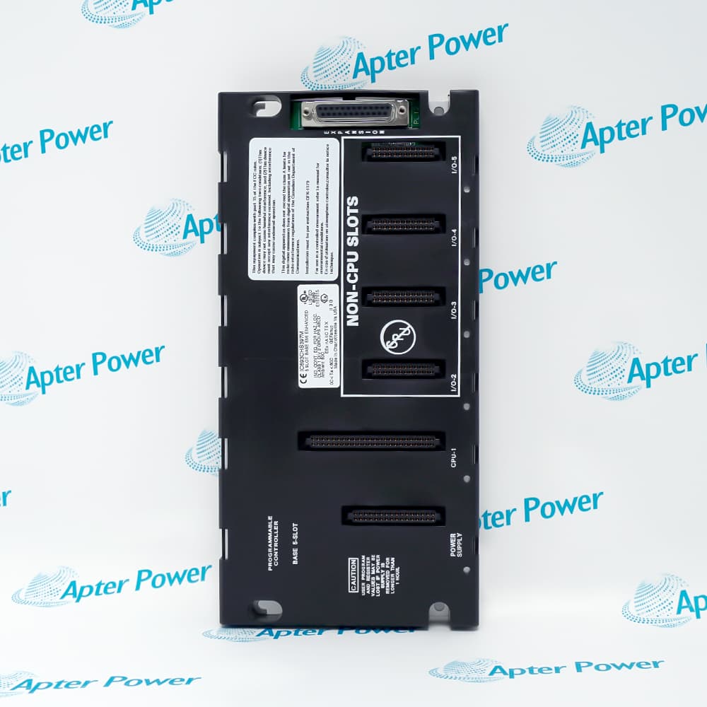
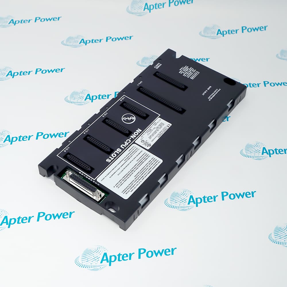
- Provides one CPU/option position and four local I/O/option positions in a compact baseplate.
- Reserves a dedicated unnumbered position for the Series 90-30 power-supply module.
- Includes the expansion connector required for supported multi-baseplate systems.
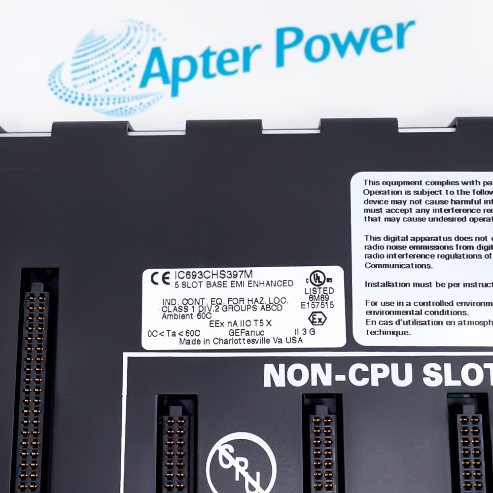
The current ordering configuration is IC693CHS397, the five-slot modular CPU baseplate assigned as rack 0 in a Series 90-30 system.
It carries the controller CPU and local module set while distributing backplane power and communication across the numbered positions.
Before replacement, document the power supply, CPU, slot order, expansion cable, downstream rack numbers, grounding and saved hardware configuration.
Availability is subject to Apter Power inventory and sourcing confirmation.
General Electric IC693CHS397 Series 90-30 5-slot CPU baseplate Manuals, Datasheets, Links
Important Notice: Other accessories, manuals, cables, calibration data, software, etc. are not included with this equipment unless listed in the above stock item description. All prices are shown in USD.
- Forms a compact main controller station for machines that fit within four local I/O or option positions.
- Anchors a larger Series 90-30 installation when additional expansion or remote baseplates are required.
- Supports retrofit of an existing five-slot modular CPU rack while preserving the documented slot layout.
- The right-hand 25-pin connector carries the Series 90-30 I/O bus to compatible downstream baseplates.
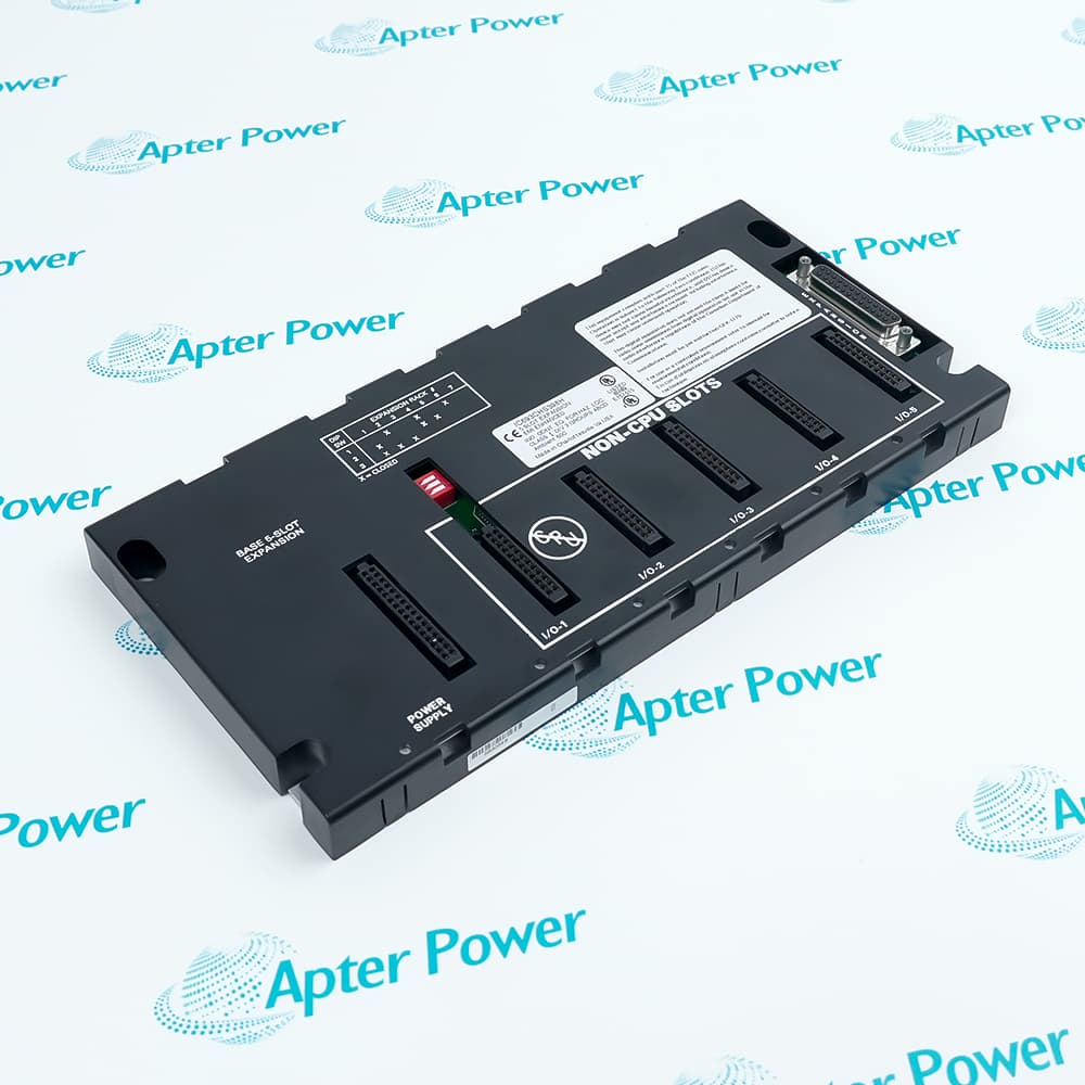
- Only the main CPU baseplate remains rack 0; every added expansion or remote baseplate follows the project rack assignment.
- The final I/O-bus connection requires the approved cable arrangement and termination described in the hardware manual.
- Five local positions suit enclosures where a ten-slot baseplate is unnecessary.
- The rack is fixed to a flat, rigid panel surface with connector clearance.
- Power is removed from the CPU baseplate before modules or expansion cables are exchanged.
- The baseplate is bonded to the common system ground before controller power is applied.
- Rack power is isolated before modules or expansion cables are removed from the controller station.
- Unused positions and hazardous-location work follow the filler-module and de-energization requirements in the installation manual.